Wall Mounted J series PCB & Algorithm
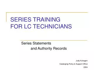
Wall Mounted J series PCB & Algorithm. PCB Layout. WM-J (10/15). Outdoor coil sensor. Indoor coil sensor. AS motor. 4WV. OD fan. Fan motor. PCB Connection Diagram (WM-J). LED Display Board. +. IR Receiver. CN_DISP. CN3. Content. 1. Features 2. Operating Modes 3. Protections.


Wall Mounted J series PCB & Algorithm
E N D
Presentation Transcript
Wall Mounted J series PCB & Algorithm
PCB Layout WM-J (10/15)
Outdoor coil sensor Indoor coil sensor AS motor 4WV OD fan Fan motor PCB Connection Diagram (WM-J) LED Display Board + IR Receiver CN_DISP CN3
Content 1. Features 2. Operating Modes 3. Protections
1. Features 1.1 Mode Selection 1.2 Power Up Settings 1.3 Unit ON / OFF 1.4 Temperature Range and Settings 1.5 Sleep Function 1.6 Indoor Fan control 1.7 Louver Control 1.8 Fan Speed Selection 1.9 Turbo Function 1.1.0 Silent Function
1. Features 1.1 Mode Selection Modes can be selected via the value of resistor RMODE MODES AUTO COOL DRY FAN HEAT DEFROST RMODE AP X XXXX C2.4 version 7.5k EC X XX open X : Modes Available
1. Features 1.2 Power UpSettings • The system is configured to memorize settings prior to power down • System will save updated settings into memory 10 seconds after changes are confirmed • However, it will take 3 seconds to update memory if unit changes from on to off state
1. Features 1.3 Unit ON / OFF • 3 ways to turn on / off the system: • (a) On/Off Triggering • Emergency On/Off Button • - System mode setting will rotate in the following • sequence • AP ….>OFF>AUTO (25°C,AUTO FAN)>OFF>….. • EC ….>OFF>COOL (25°C,AUTO FAN)>OFF>….. • On/Off button on wired (not applicable at the moment) / wireless controller
1. Features 1.3 Unit ON / OFF • (b) Delay timer • Pressing the On/Off will reset the timer to 0 hour (not applicable at the moment) • (c) Real time On/Off Timer • Based on internal real time clock • The timer settings are kept so that similar switches can occur 24 hours later • If emergency ON/OFF switch being press, then the timer will be deactivated Operation ON/OFF LED and buzzer respond in different way during mode change
1. Features 1.4 Temperature Range and Settings • operating temperature range is 16°C to 30°C • temperature setting is allowed in COOL, DRY, HEAT and AUTO modes
1. Features 1.5 Sleep Function • Only available for COOL, HEAT & AUTO mode • This function will increase 2°C(cooling mode) or decrease 3°C (Heating mode) of the set temperature with time • Change to another modes will inhibit SLEEP function and reset the timer
1. Features 1.5 Sleep Function (Cool Mode)
1. Features 1.5 Sleep Function (Heat Mode)
1. Features 1.6 Indoor Fan Control • Indoor fan speeds are SILENT,LOW, MED, HIGH, TURBO or AUTO FAN in COOL and HEAT modes • In FAN mode, only HI, MED and LO speeds are allowed
1. Features 1.7 Louver Control • Stepper motor will only run when indoor fan runs • Louver is set at max. closing position when unit is turned off • If unit switches from OFF mode to ON mode, the louver will stop at the last position when it goes from ON to OFF mode.
1. Features 1.8 Fan Speed Selection • In COOL and HEAT, the indoor fan speeds are SILENT, LO, MED, HIGH, TURBO or AUTO FAN • In FAN mode, only HI, MED and LO speeds are allowed
1. Features 1.9 Turbo Function • Available in COOL and HEAT modes • When Turbo function is set, indoor fan will force to Turbo fan for 20 minutes and working temperature for - Cooling Cycle is offset Ts – 2˚C - Heating Cycle is offset Ts + 2˚C • If Turbo & Sleep function are activated at the same time, Sleep • mode timer will reset until Turbo function is clear
1. Features 1.1.0 Silent Function • Available in COOL and HEAT modes only • When Silent function is set, indoor fan will force to Silent fan
2. Operating Mode 2.1 Cool Mode 2.2 Dry Mode 2.3 Fan Mode 2.4 Heat Mode 2.5 Defrost Mode 2.6 Auto Mode 2.7 Off Mode
2. Operating Modes Cold Start • Cold start if: Units restarts 2 hours after it has stopped OR during power-on reset start • Not available in sleep mode, only available in heat and cool mode • In cooling mode, offset temperature is -2°C • In heating mode, offset temperature is +2 • After 20 minutes running or compressor cut-off (whichever earlier), cold start will be terminated and resume to user setting
Compressor will cut in if Tr – Ts > 0.5˚C Compressor will cut out if Tr < Ts – 1.0˚C Note: Tr = Room Temperature Ts = Set Temperature 2. Operating Modes 2.1 Cool Mode
2. Operating Modes 2.2 Dry Mode During the 1st 12 minutes of the DRY mode run from: • i) Cold start OR • ii) Mode change from HEAT, FAN or AUTO HEAT • DRY mode must run under COOL mode with Auto Fan Speed for 12 minutes OR • Run Until Tr < Ts – 1°C After the 1st 12 minutes • DRY mode will run either Zone A, B, C or D (depend on temp. condition)
2. Operating Modes 2.2 Dry Mode ZONE A : if Tr - Ts > 2 o C ON Compressor OFF ON Low Fan OFF 12 Minutes
2. Operating Modes 2.2 Dry Mode ZONE B : if 0°C < Tr - Ts < 1°C ON Compressor OFF 4 min 8 min ON Low Fan OFF 30 sec 30 sec 12 Minutes
2. Operating Modes 2.2 Dry Mode ZONE C : if 1°C < Ts - Tr < 2°C ON Compressor OFF 6 min 6 min ON Low Fan OFF 12 Minutes 30 sec 30 sec
2. Operating Modes 2.2 Dry Mode ZONE D : if Ts - Tr > 3°C ON Low Fan OFF 30 sec ON Compressor OFF 12 Minutes
2. Operating Modes 2.3 Fan Mode • Only HI, MED and LO speeds are allowed • The compressor and the outdoor fan will stop • The 4-way valve will turn off also
2. Operating Modes 2.4 Heat Mode • Compressor will cut in if Tr < Ts + 1.0˚C • Compressor will cut out if Tr –Ts > 3.5˚C Note: Tr = Room Temperature Ts = Set Temperature 2.4.1 Heat Pump Model
2. Operating Modes 2.4 Heat Mode • The indoor fan speed modulate according to the Tin coil: - If Tin coil > 40˚C, indoor fan run at user set speed - If Tin coil < 18˚C, indoor fan stop - If Tin coil crosses 30˚C, indoor fan change to silent fan speed Note : Tin coil = Indoor Coil Temperature 2.4.2 Hot Start
2. Operating Modes 2.4 Heat Mode When compressor cuts out, the indoor fan will runs according to hot keep options There are only 1 option of Hot Keep: Fan Off Option 2.4.3 Hot Keep
2. Operating Modes 2.4 Heat Mode Fan Off Option • If Tin coil > 40˚C, indoor fan run at set speed • If Tin coil crosses 37˚C, indoor fan run at silent speed • If Tin coil < 30˚C, indoor fan stop 2.4.3 Hot Keep
2. Operating Modes 2.4 Heat Mode • To run heat mode, 4-way valve MUST turn ON • 4-way valve can only be changed from ON to OFF or vice-versa 150 seconds after the compressor has cut out • Then the compressor cut in after 4 sec 2.4.4 4-Way valve Changing
Defrost mode can only be declared under heat mode Defrost timer start counting when OD coil temperature < +3°C Upon crossing over +5°C or higher more than 150 sec, timer will reset Temperature sensing can be done only when compressor run time > 2 min 2. Operating Modes 2.5 Defrost Mode
2. Operating Modes To °C +3 +2 C P13 P17 0 0 P15 time P16 B P14 A P12 Defrost mode if more than 3 minutes 2.5 Defrost Mode
i) 30 mins to 60 mins below +3°C, if OD coil temperature is <=-8°C for > 3 min (compressor ON) ii) 60 mins to 120 mins below +3°C, if OD coil temperature is <=-4°C for > 3 min (compressor ON) iii) >120 mins below +3°C, if OD coil temperature is <=-2°C for > 3 min (compressor ON) If unit in OD fan forced off mode, defrost mode is not allowed to declare 2. Operating Modes 2.5 Defrost Mode Defrost mode will start if compressor run time is :
RMODE 7.5k ohm resistor Indoor fan, auxiliary heater, outdoor fan, 4WV cut off while compressor remain on Defrost mode terminate when 1) OD coil temperature > 10°C or 2) minimum 10 minutes compressor run time Compressor cut out at the end of defrost cycle, 4WV on after 50 seconds Compressor can cut in after 10 seconds 2. Operating Modes Defrost Cycle C2.4 version
2. Operating Modes 2.6 Auto Mode Under Auto mode, COOL & HEAT mode can be changed automatically depending on room & set temperature (a) If the present Auto mode is COOL, ( Mode Set Temperature = User Set Temperature) COOL HEAT IF • Tr <= Ts mode- 3.5°C AND • The compressor has cut out for at least 10 mins
2. Operating Modes 2.6 Auto Mode (b) If the present Auto mode is HEAT, ( Mode Set Temperature < User Set Temperature-1.5°C) HEAT COOL IF (i) Tr > Ts mode + 3°C AND (ii) The compressor has cut out for at least 10 mins
2. Operating Modes 2.7 Off Mode • No LED indication when unit is turned off • All relays is turned off immediately after ON/OFF triggering except 4-way valve (subject to 4WV switching time protection)
3. Protections 3.1 Compressor 3.2 Outdoor Fan Speed Control 3.3 Indoor Anti Freeze 3.4 Gas Leak (Outdoor unit abnormal) 3.5 Fan Lock
3. Protections 3.1 Compressor • (a) 3 minutes Minimum OFF time • Compressor can only cut in after a minimum period of 3 mins from the time it cuts off except during valve changeover sequences • There shall have a minimum delay timer of 2 sec between outdoor fan & compressor when both turn on
3. Protections 3.1 Compressor • (b) Compressor Random Restart • With memory backup selection, compressor cut in 0-64 sec after power up again • Compressor cut in is subjected to thermostat cut in mode
3. Protections 3.1 Compressor • (c) Compressor Minimum Run Time • Compressor can only cut out after minimum 3 mins of running in current mode • Compressor can cut out at any time is system is switched to other modes or other protection sequences • (d) Compressor Overload Protection • Method to detect compressor overload is by coil sensor detection
3. Protections 3.1 Compressor (e) Coil Sensors Detection Cooling Cycle Comp & OD Fan ON OFF 68 o C OD coil temp Heating Cycle Comp, OD Fan & 4WV ON OFF 68 o C ID coil temp
3. Protections 3.2 Outdoor Fan Speed Control (a) Heating Mode • Outdoor fan will cut off, if indoor coil temperature > 55˚C • Outdoor fan will resume, if indoor coil temperature < 50˚C (b) Cooling Mode • Outdoor fan will run when compressor has cut in
ON Comp & OD Fan OFF 1oC Comp & OD Fan ON OFF 10oC 3. Protections 3.3 Indoor Coil Anti Freeze • Available in COOL mode only • IF ID Coil Temp reaches 1°C and below for at least 1 min • AND compressor has run for at least 10 minutes • IF ID Coil Temp reached 10˚C and above for at least 1 min
3. Protections 3.4 Gas Leak (Outdoor unit abnormal) • This option is selected via resistor RGL • Gas leak is declared if ID coil temp. is >25°C in cooling cycle OR < 20°Cin heating cycle • System will check the gas leak mode if compressor run time of 30 mins achieved • If these condition is met, the system will reconfirm ID coil temperature for 5 mins in cool mode OR 5 mins in heat mode before declaring gas leak mode • No gas leak checking during outdoor defrost. Compressor run timer is reset
3. Protections 3.5 Fan Lock • When there is no feedback from ID fan, unit will wait for 10 sec • After 10 sec, counter in the software will increase by one • Then LED will start blinking to indicate error of the unit while the compressor and OD fan are allowed to on depend on thermostat cycle • If there is no fan speed feedback error continue for another 30 sec, compressor and OD fan will be forced off • LED will continue blinking and louver is allowed to operate