Download
1 / 106
1.06k likes | 1.08k Views
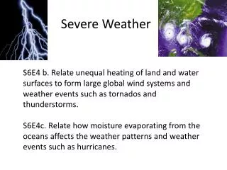
This movie showcases severe weather patterns in southern Colorado and western Kansas using GOES and radar animation. It highlights the nighttime flow of moisture into Texas and the transition from moist to dry boundary layer air over West Texas. The presentation focuses on tornado-producing storms but can be generalized for supercell storms. It covers various factors such as vertical shear, evolving instability field, updraft strength, anvil characteristics, and storm damage.

E N D
Movie showing GOES and radar animation over the same area (southern Colorado and western Kansas) and at the same time.
Transition from moist to dry boundary layer air over West Texas – daytime to night
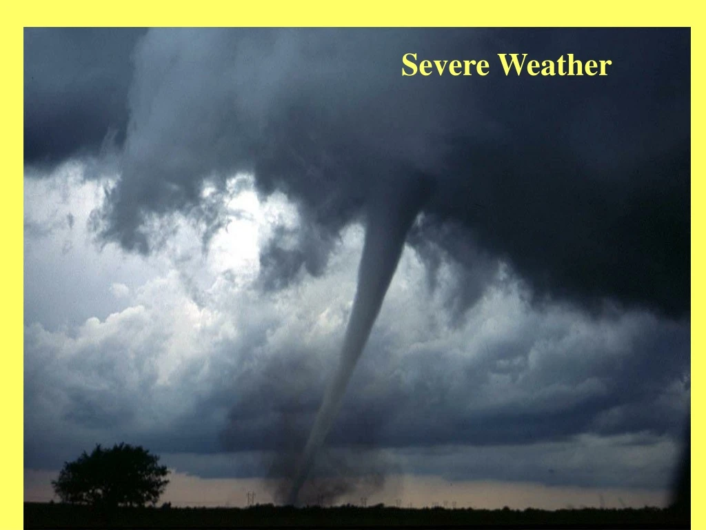
Severe Thunderstorms • This presentation on satellites and severe thunderstorms follows is meant to address tornado producing storms, but may be generalized for super cell type storms. • One should familiar with the principals developed in the general convection presentation.
Vertical shear ABI (cloud motion) HES-IR (moisture motion) HES-VNIR (cloud and moisture motion) Evolving instability field ABI (surface heating) HES-IR (instability and surface heating) HES-VNIR (detailed moisture field) Cold pool production HES-IR Updraft strength ABI (IR top temperature) ABI and HES-VNIR (overshooting top height) Above with HES-IR (updraft efficiency) Anvil characteristics & storm environment interaction ABI (growth and detailed upper level atmospheric motion and water vapor behavior) HES-IR and VNIR (as ABI but with better spectral definition) Rotating overshooting top ABI and HES-VNIR Storm damage HES-VNIR Nowcasting requires detailed information on mesoscale thermodynamic structure of atmosphere, cloud type and vertical wind shear Convection and Severe Weather • Important for Nowcasting Convection and Severe Weather • Vertical wind shear • Evolving instability field • Strength of storm produced cold pool • Updraft strength • Anvil characteristics • Development • Temperature structure • Storm-environment interaction • Cloud top rotation • Storm damage
Severe Thunderstorms Note the cold pool left behind by the storm, as well as convective tower growth. This 4 panel movie illustrates the difference between movies made with 1, 5, 15 and 30 minute interval imagery.
GOES: Imager and sounder Instability field from GOES over severe storm area and severe storm at one minute interval (right)
Vorticity - On the local scale • Convergence on preexisting vorticity • Tilting of vorticity from one plane to another • Advection from one place to another • Differential heating • Friction
Severe Storms Like Boundaries • Interaction along a boundary depends on both the storm’s and boundaries characteristics
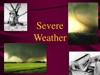
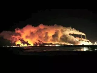
Wichita Falls tornado (F5) approaching a subdivision where it destroied most of the houses. Note the multiple funnel vortices.
A house, cars, gas station and nearby Trade Winds Motor Hotel about to be destroyed in Wichita Falls.
Role of Mesoscale Convective System in Jarrell tornadic storm development
Jarrell tornadic storm system – GOES instability development
April 21, 1991 Tornado Outbreak • 2 km visible • 1831-0030 Z • Earth Relative Motion • Main severe outbreak across Kansas & Oklahoma • Note cirrus motion and squall line development
April 21, 1991 Tornado Outbreak • 1 km visible zoomed to ½ km scale • 1831-0030 Z • Earth Relative Motion • Across Kansas & Oklahoma boarder • Note cumulus flow, overshooting tops and cirrus motions
April 21, 1991 Tornado Outbreak • 1 km visible zoomed to ½ km scale • 1841-2030 Z • Storm Relative Motion • Across Kansas & Oklahoma boarder • Note low level moist flow and shear in cloud layer relative to developing storms and storm effect on low level environment
April 21, 1991 Tornado Outbreak • 1 km visible • 1841- 0001 Z • Storm Relative Motion • Across Kansas & Oklahoma boarder • Note low level moist flow and shear in cloud layer relative to developing storms and storm effect on low level environment
April 21, 1991 Tornado Outbreak • 1 km visible • 2026-0001 Z • Cirrus Relative Motion • Note storm effect on upper flow
Note the “capped” cumulus cloud streets ahead of the squall line
Different visible enhancements 1 - none, 2 - linear min to max3 - dual stretch min to max using temperature threshold
Comparison of visible enhancementstop - none versus linearbottom - linear versus dual with temperature threshold
Different visible enhancements 4a - none, 4b - linear min to max, 4c - dual stretch min to max using temperature threshold
Different characteristics of anvils and overshooting tops are revealed by using different channels. Shown here are AVHRR visible (upper left), 3.7 microns (upper right with special enhancement across anvil top) and 10.7 micron IR