Download
1 / 25
250 likes | 434 Views
Experience in Design and Implementation of CO 2 Cooling Control Systems . Lukasz Zwalinski PH/DT /PO - Cooling. Presentation overview . Introduction CO 2 cooling systems control principle Control system standardization approach CO 2 cooling test stands at CERN

E N D
Experience in Design and Implementation of CO2 Cooling Control Systems Lukasz Zwalinski PH/DT/PO - Cooling
Presentation overview • Introduction • CO2 cooling systems control principle • Control system standardization approach • CO2cooling test stands at CERN • 2kW CORA – ATLAS and CMS (PH-DT-PO) • 100W TRACI – ATLAS & LHCb (PH-DT-PO) • 2kW CO2 SR1 – ATLAS (EN-CV-DC & PH-DT-PO) • What’s next? Detector Seminary 11th October 2011 L.Zwalinski – PH/DT/PO
Introduction • Why CO2? • Allows very small tubing (material budget) • High heat transfer coefficient • High thermal stability due to the high pressure • Where currently successfully used? • AMS-TTCS (Tracker Thermal Control System) • Q = 150 W • T = +15 ºC to -20 ºC • LHCb-VTCS (Velo Thermal Control System) • Q = 1500 W (2 parallel systems of 750 W) • T = +8 ºC to -30 ºC • CO2 cooling systems under development • ATLAS IBL • CMS - tracker upgrade • KEKb-Bell 2 Detector Seminary 11th October 2011 L.Zwalinski – PH/DT/PO
Principle Refrigeration method: (Atlas) Vapor compression system Liquid Vapor Compressor Heater Pressure Warm transfer BP. Regulator 2-phase Cooling plant Detector Enthalpy 2-Phase Accumulator Controlled Loop method: (LHCb) Pumped liquid system, cooled externally Liquid Vapor Compressor Pump Pressure Chiller Liquid circulation Cold transfer 2-phase Enthalpy Cooling plant Detector Detector Seminary 11th October 2011 L.Zwalinski – PH/DT/PO
Introduction to control CO2 cooling system 7 Heating Cooling Accumulator Pressure Cooling regulated by pulse modulated control valve Gas 2 3 2 3 2 3 Heating – regulated by pulse modulated heater Liquid 7 1 6 4&5 7 Chiller 1 6 4&5 2-phase (Evaporation) Heaters 7 1 6 4&5 Isothermal line Enthalpy Pump Control valves 5 6 Pump 2 4 3 1 Detector Seminary 11th October 2011 L.Zwalinski– PH/DT/PO
Control system standardization approach • Why do we need standardization? • To design and fully test complete base model of future detector cooling systems (mechanical/electrical/control) • Provide a control system in accordance with CERN standards • Provide a system easy to integrate with Detector Control System • How do we apply it? • Common and easy to manipulate human machine interface for PLC based systems with long term data archiving, trending tools, alarms history and diagnostic tools. PVSS as supervision and data acquisition system well known and widely used at CERN in LHC and in Detector Control Systems (ATLAS) • Industrial control/electrical components: Siemens/Schneider/Phoenix/PR electronics • UNifiedIndustrial COntrolSystem framework – object orientated framework for PLC and PVSS programming Detector Seminary 11th October 2011 L.Zwalinski – PH/DT/PO
Standardization approach Industrial electrical components Control hardware equipment Electrical diagnostic tools Siemens PLC standard UNICOS framework IEC61512-1 standard PVSS Schneider PLC standard CO2 Recipes component • New software components: • on-line pressure enthalpy diagram • one button PVSS system start/stop • Alarm diagnostic Detector Seminary 11th October 2011 L.Zwalinski – PH/DT/PO
Control system design and implementation Process concept Work flow for control system design and implementation PLC programming Functional analysis SCADA programming Electrical design UNICOS Electrical assembly Additional tools development Assembly User manual Project organization Commissioning Component selection and ordering Detector Seminary 11th October 2011 L.Zwalinski – PH/DT/PO
CORA 2kW – control system architecture • CO2Research Apparatus - CORA • Siemens S7 319 PLC (building 158) • PVSS 3.8 data server on Windows PC (building 21) • UNICOS framework (32AI, 4AO,32DI, 32DO, 7 closed control loops) • Experiment power redistribution box with temperature protection OWS OWS OWS B21 GPN Power permit SIEMENS PLC Test structure Electrical / signal connections TT protection B158 Detector Seminary 11th October 2011 L.Zwalinski – PH/DT/PO
CORA 2kW – control system Detector Seminary 11th October 2011 L.Zwalinski – PH/DT/PO
CORA 2kW – control system Alarm diagnostic Alarm list + email & SMS alarm notification Detector Seminary 11th October 2011 L.Zwalinski – PH/DT/PO
CORA 2kW – control system PLC graph Electrical diagnostic System stepper Detector Seminary 11th October 2011 L.Zwalinski – PH/DT/PO
CORA 2kW – accumulator control To avoid of overheating (dry out prevention) To keep sub cooling condition Detector Seminary 11th October 2011 L.Zwalinski – PH/DT/PO
CORA 2kW – pressure, enthalpy online diagram • PVSS control extension: • Real time calculation • Connection to external data base REFPROP 8 • 11 constantly plotted isotherms • Possibility of displaying isotherms in measured points • Proposed as future JCOP component • Point 1 - Outlet of experiment lines • Point 2 - Outlet of return line of internal heat exchanger • Point 3 - Pump inlet • Point 4 - Pump outlet • Point 5 - Outlet of supply line of internal heat exchanger • This control extension currently is available on Windows machine only! 4 5 2 1 3 Detector Seminary 11th October 2011 L.Zwalinski – PH/DT/PO
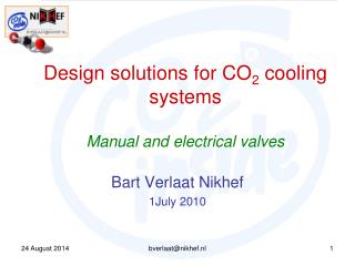
100W TRACI - concept Transportable Refrigeration Apparatus for CO2Investigation Simplified concept of 2 Phase Accumulator Controlled Loop To simplify the concept the internal heat exchanger function and the accumulator cooling function are integrated by cooling the accumulator with the pump outlet flow. The concept is called Integrated 2PACL (I-2PACL). The simplified concept was patented on Friday September 9th, 2011. I-2PACL 2PACL Detector Seminary 11th October 2011 L.Zwalinski – PH/DT/PO
100W TRACI – control system • Requirements: • Simplified control concept = NOPLC! • Solution: • On-shelf industrial control/electrical components • All logic realized by relays, universal transmitters and 1 PID controller • Integrated National Instruments DAQ • LabVIEW user interface, open to add experimental part • No need to have PC/PVSS to run the plant Detector Seminary 11th October 2011 L.Zwalinski – PH/DT/PO
100W TRACI – first results and future improvements • Goal: 100W @ -40oC to +20oC • -40ºC not met • More heatleakthan expected • 1.5x larger chiller possible in same mechanical envelope • Future control improvements: • Reduce electronics to micro-controller • Skip some functionalities in control • Replace pump to be fixed speed (no frequency control) • More powerful chiller 150W heat load 150W heat load Detector Seminary 11th October 2011 L.Zwalinski – PH/DT/PO
CO2 SR1 concept – collaboration with EN-CV-DC Differences to CORA accumulator design dummy load design primary chiller PLC brand Detector Seminary 11th October 2011 L.Zwalinski – PH/DT/PO
CO2 SR1 - control system based on CORA experience Modifications Schneider PLC (EN-CV-DC hw. standard) Main user SCADA panel PROFIBUS flow meters CERN Terminal Server OWS OWS OWS 1. CO2 2. Mélangues 3. Thermosiphon 2kW Architecture CERN GPN CERN TN CPU + I/O cards • UNICOS based PLC software • UNICOS based PVSS implementation CPU + I/O cards CPU + I/O cards • One central PVSS data server in BE-CO for all “test” applications • Access to all applications form one terminal server • PVSS accesses control with personal NICE login and password • All applications in Technical Network CO2 Melangues Thermosiphon 2kW Detector Seminary 11th October 2011 L.Zwalinski – PH/DT/PO
CO2 SR1 PVSS interface based on CORA experience Modifications Recipes Interlocks diagnostic Electrical diagnostic Accumulator limiters Stepper Detector Seminary 11th October 2011 L.Zwalinski – PH/DT/PO
Functional analysis and control Modifications based on CORA experience • Functional analysis: • process • actuator operation logic • system states and transitions • alarms • computed parameters • recipes parameters • https://espace.cern.ch/CO2-SR1/Shared%20Documents/Control/CO2_SR1_Functional_Analysis.doc Detector Seminary 11th October 2011 L.Zwalinski – PH/DT/PO
What’s next? • MARCO: Multipurpose Apparatus for Research on CO2 • 2PACL concept • Temperature range from -40C to room temperature • Capacity 1kW • Base for future ATLAS IBL and KEKb-Bell 2 detectors • Control system approach: • Control system to be easily integrated in DCS • Siemens PLC • UNICOS framework • Integrated control panel (to be introduced, currently not supported solution) • Use recipe component • Select tested in previous CO2 cooling units electrical and control components • Status: • PLC components delivered • Electrical study in progress (electrical schematics) Detector Seminary 11th October 2011 L.Zwalinski – PH/DT/PO
Conclusions • Existing test CO2 cooling stations at CERN: • CORA operational • TRACI 1a(LHCb) and TRACI 1b(ATLAS) operational • CO2 SR1 under commissioning • MARCO under construction • CO2 cooling systems in HEP experiments: • AMS • LHCb Detector Seminary 11th October 2011 L.Zwalinski – PH/DT/PO
CORA 2kW – experiment inlet enthalpy control Øm = Qexperimet / (h5 - h4) Qheater = (hrequested - h3) * Øm It is not possible directly control the enthalpy in a PID loop. The enthalpy can be derived from measured pressure and temperature only when the state point is present in the liquid phase which means that measured temperature should be at least 20C lower than calculated Tsat . PLC is calculating enthalpy from measured temperature TT1104 and pressure PT1102 and it’s ON only if TT1104 -20C ≤ Tsat(PT1102)is true. Measured pressure => look for p_up & p_down in table and associated A,B,C,D up& down constants h_up := A_up*(input_TT**3) + B_up*(input_TT**2) + C_up*input_TT + D_up; h_down := A_down*(input_TT**3) + B_down*(input_TT**2) + C_down*input_TT + D_down; //Enthalpy search, interpolation Output:= ((h_up-h_down)*(input_PT-input_PT_down)/(input_PT_up-input_PT_down))+h_down; Detector Seminary 11th October 2011 L.Zwalinski – PH/DT/PO
CORA 2kW – experiment inlet enthalpy control CO2 allows small tubing Why? Large latent heat & Low viscosity & High pressure Allow high pressure drop Low pressure drop Allow low flow Lower pressure drop Low pressure drop Allow very small tubing Liquid Viscosity Latent Heat of Evaporation 5e-4 C3F8 300 But with very high heat transfer capability! 4e-4 CO2 Better CO2 (KJ/kg) 3e-4 Better 200 (Pa*s) Better C3F8 CO2 2e-4 100 C3F8 1e-4 0 -20 20 -40 0 -20 20 -40 0 Detector Seminary 11th October 2011 L.Zwalinski – PH/DT/PO Temperature (ºC ) Temperature (ºC )