Compiler and Debugger
Learn about debugging skills for ARM processors, memory configuration, software estimation, and profiling to improve software quality. Understand ARM debug target usage and memory mapping. Estimate software costs, code sizes, and performance benchmarks.


Compiler and Debugger
E N D
Presentation Transcript
Compiler and Debugger Speaker: Chun-Yao Wang
Goal of this Lab • ARM Debug Target • Usage of different ARM debug architecture • Debug skills to be used to debug both software of processor and memory-mapped hardware design running at the target platform. • Software cost estimation • Estimation of code sizes and performance of benchmark • Profiling utility • Can be used to estimate percentage time of each function in an application • Memory configuration • For performance/cost trade-off
Outline • Introduction • ARM Debug Target • Debugging Skills • Software Quality Measurement (Evaluation) • Appendix • Reference
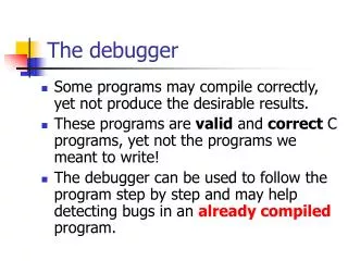
Introduction (1/2) • A debugger is software that enables you to make use of a debug agent in order to examine and control the execution of software running on a debug target. • The debugger issues instructions that can: • Load software into memory on the target • Start and stop execution of that software • Display contents of memory, registers, variables • Enable you to change stored values. • Software Quality Measurement ( code size, performance, profiling.. )
Introduction (2/2) ARM support two methods to do debugging. • GUI : ARM eXtended Debugger (AXD). • DOS : ARM Symbolic Debugger (armsd). AXD armsd
ARM Debug Target • AXD can debug design through: • ARMulator (software) • Multi-ICE (hardware) • use JTAG • Angel (hardware) • Use COM port
Multi-ICE Arch. (1/3) • Multi-ICE connection
Multi-ICE Arch. (2/3) • Debugging software can be run on different computer through Network.
Multi-ICE Arch. (3/3) • To support network connections, an additional application must be running on the windows workstation that runs the The multi-ICE server. • the portmapper allows software on other computers on the network to locate the The multi-ICE server.
Debugging Skills • Control of program execution • set breakpoints on interesting instructions • set watchpoints on interesting data accesses • single step through code • Examine and change processor state • read and write register values • Examine and change system state • access to system memory • Interleaving source code • show C/C++ code and assemble code together
Watch / Break Point • Watchpoints are taken when the data being watchpointed has changed. • Breakpoints are taken when the instruction being breakpointed reaches the execution stage. the program counter is not updated, and retains the address of the breakpointed instruction.
Software Quality Measurement • Memory requirement of the program • Data type: Volatile (RAM), non-volatile (ROM) • Memory performance: access speed, data width, size and range • Profiling • build up a picture of the percentage of time spent in each procedure. • Performance benchmarking • Evaluate software performance prior to implement on hardware • Writing efficient C for ARM cores • ARM/Thumb interworking • Coding styles
Application Code and Data Size • armlink offers two options to provide the relevant information: • -infosizes (sizes of all objects) • -info totals (summary only) ============================================================ Image component sizes Code RO Data RW Data ZI Data Debug 25840 3444 0 0 104344 Object Totals 22680 762 0 300 9104 Library Totals ============================================================= Code RO Data RW Data ZI Data Debug 48520 4206 0 300 113448 Grand Totals ============================================================= Total RO Size(Code + RO Data) 52726 ( 51.49kB) Total RW Size(RW Data + ZI Data) 300 ( 0.29kB) Total ROM Size(Code + RO Data + RW Data) 52726 ( 51.49kB) ============================================================= • The size of code/data in • an ELF image can be viewed using fromelf –z • a library can be viewed using armar –sizes
ARM and Thumb Code Size The equivalent ARM assembly Iabs CMP r0,#0 ;Compare r0 to zero RSBLT r0,r0,#0 ;If r0<0 (less than=LT) then do r0= 0-r0 MOV pc,lr ;Move Link Register to PC (Return) Simple C routine if (x>=0) return x; else return -x; The equivalent Thumb assembly CODE16 ;Directive specifying 16-bit (Thumb) instructions labs CMP r0,#0 ;Compare r0 to zero BGE return ;Jump to Return if greater or ;equal to zero NEG r0,r0 ;If not, negate r0 return MOV pc,lr ;Move Link register to PC (Return)
Memory Map and Size Considerations RAM • The linker calculates the ROM and RAM requirements for code and data as follows: • ROM: Code size + RO data + RW data • RAM: RW Data + ZI data. • You may wish to copy code from ROM into faster RAM, which will also increase the RAM requirements • Placing the stacks in zero-wait state, 32-bit memory on-chip will significantly improve over 8 or 16- bit off-chip memory ROM Default memory map
Profiling (1/3) • About Profiling: • Profiler samples the program counter and computes the percentage time of each function spent. • Flat Profiling: • If only pc-sampling info. is present. It can only display the time percentage spent in each function excluding the time in its children. • Flat profiling accumulates limited information without altering the image • Call graph Profiling: • If function call count info. is present. It can show the approximations of the time spent in each function including the time in its children. • Extra code is added to the image
Profiling (2/3) • Profiling Limitations: • Profiling is NOT available for code in ROM, or for scatter loaded images. • No data is gathered for programs that are too small. Flat Profiling Call graph Profiling
Profiling (3/3) cumulative • The Profiler command syntax is as follows: armprof [-parent|-noparent][-child|-nochild][-sort options] prf_file • Call graph Profiling Sample Output Name cum% self% desc% calls --------------------------------------------------------------------- main 17.69% 60.06% 1 insert_sort 77.76% 17.69% 60.06% 1 strcmp 60.06% 0.00% 243432 --------------------------------------------------------------------- qs_string_compare 3.21% 0.00% 13021 shell_sort 3.46% 0.00% 14059 insert_sort 60.06% 0.00% 243432 strcmp 66.75% 66.75% 0.00% 270512 --------------------------------------------------------------------- self descendants calls
Performance Benchmarking (1/4) • Execution time ( real-time vs. emulated ) • $sys_clock • Execution time = Total Cycle count / Cycle Frequency
Performance Benchmarking (2/4) • When ARM processor executes program, it will change these clock types according to demand of operating. • Increase performance of data access • Efficient mechanism of lower power • N-cycles (Non-sequential cycle)The ARM core requests a transfer to or from an address which is unrelated to the address used in the preceding cycle. • S-cycles (Sequential cycle)The ARM core requests a transfer to or from an address which is either the same, or one word or one-half-word greater than the preceding address. • I-cycles (Internal cycle or Idle cycle) The ARM core does not require a transfer, as it is performing an internal function. • C-cycles (Coprocessor register transfer cycle) • Total clock cycle = (N + S + I + C)-cycles
Performance Benchmarking (3/4) Estimation using different Memory model • If no map file is specified: • ARMulator will use a 4GB bank of ‘ideal’ memory, i.e., no wait states. • The map file defines regions of memory, and, for each region: • The address range to which that region is mapped. • The data bus width (in bytes). • The access times for the memory region (in ns) • mapfile typically contains something like: 00000000 00020000 ROM 2 R 150/100 150/100 10000000 00008000 RAM 4 RW 100/65 100/65 start address, length, label, width, access, read time, write time type non-s/seq non-s/seq
Performance Benchmarking (4/4) Benchmarking cached cores • Cache efficiency • Avg. memory access time = hit time +Miss rate x Miss Penalty • Cache Efficiency = Core-Cycles / Total Bus Cycles
Writing Efficient C for ARM Cores • ARM/Thumb interworking • ARM : Bottleneck, interrupt handle • Thumb: others • Compiler optimization: • Space or speed (e.g, -Ospace or -Otime) • Debug or release version (e.g., -O0 ,-O1 or -O2) • Instruction scheduling • Coding style • Variable type and size • Parameter passing • Loop termination • Division operation and modulo arithmetic
a pad b c pad d Data Layout Default char a; short b; char c; int d; Optimized char a; char c; short b; int d; a c b d occupies 8 bytes, without any padding occupies 12 bytes, with 4 bytes of padding Group variables of the same type together. This is the best way to ensure that as little padding data as possible is added by the compiler.
Variable Types – Size Examples int wordinc (int a) { return a + 1; } wordinc ADD a1,a1,#1 MOV pc,lr shortinc ADD a1,a1,#1 MOV a1,a1,LSL #16 MOV a1,a1,ASR #16 MOV pc,lr short shortinc (short a) { return a + 1; } charinc ADD a1,a1,#1 AND a1,a1,#&ff MOV pc,lr char charinc (char a) { return a + 1; }
Stack Usage • C/C++ code uses the stack intensively. The stack is used to hold: • Return addresses for subroutines • Local arrays & structures • To minimize stack usage: • Keep functions small (few variables, less spills)minimize the number of ‘live’ variables (I.e., those which contain useful data at each point in the function) • Avoid using large local structures or arrays (use malloc/free instead) • Avoid recursion
Global Data Issues • When declaring global variables in source code to be compiled with ARM Software, three things are affected by the way you structure your code: • How much space the variables occupy at run time. This determines the size of RAM required for a program to run. The ARM compilers may insert padding bytes between variables, to ensure that they are properly aligned. • How much space the variables occupy in the image. This is one of the factors determining the size of ROM needed to hold a program. Some global variables which are not explicitly initialized in your program may nevertheless have their initial value (of zero, as defined by the C standard) stored in the image. • The size of the code needed to access the variables. Some data organizations require more code to access the data. As an extreme example, the smallest data size would be achieved if all variables were stored in suitably sized bitfields, but the code required to access them would be much larger.
Loop Termination … int acc(int n) { int i; //loop index int sum=0; for (i=n; i!=0 ;i--) sum+=i; return sum; } … … int acc(int n) { int i; //loop index int sum=0; for (i=1; i<=n ;i++) sum+=i; return sum; } … loop.c loop_opt.c
Division Operation and Modulo Arithmetic • The remainder operator ‘%’ is commonly used in modulo arithmetic. • This will be expensive if the modulo value is not a power of two • This can be avoid by rewriting C code to use if () statement heck unsigned counter1 (unsigned counter) { return (++counter % 60); } ============================= counter1 STMFB sp!, {lr} ADD r1, r0, #1 MOV r0, #0x3C BL __rt_udiv MOV r0, r1 LDMIA sp!, {pc} unsigned counter2 (unsigned counter) { if (++counter >= 60) counter=0; return counter } ============================= counter2 ADD r0, r0, #1 CMP r0, #0x3C MOVCS r0, #0 MOV pc, lr modulo_opt.c modulo.c
Appendix • Content of JTAG • Content of Embedded ICE
Content of JTAG (I) • JTAG Arch. • Serial scan path from one cell to another • Controlled by TAP controller
Content of JTAG (III) • Boldface represents that these pins are JTAG Signals
Content of Embedded ICE (I) • Debug extensions to the ARM core • The extensions consist of a number of scan chains around the processor core and some additional signals that are used to control the behavior of the core for debug purposes : • BREAKPT: enables external hardware to halt processor execution for debug purposes.active high • DBGRQ: is a level-sensitive input that causes the CPU to enter debug state when the current instruction has completed. • DBGACK: is an output from the CPU that goes high when the core is in debug state
Content of Embedded ICE (II) • The EmbeddedICE logic • This logic is the integrated onchip logic that provides JTAG debug support for ARM core. • This logic is accessed through the TAP controller on the ARM core using the JTAG interface. Consists of: • Two watchpoint units • A control register • A status register • A set of registers implementing the Debug Communications Channel link
Reference • Profiling: “Application Note 93: Benchmarking with ARMulator” • Efficient C programming: “Application Note 34: Writing Efficient C for ARM” • Multi-ICE.pdf • ADS_DebuggersGuide.pdf • ADS_GettingStarted.pdf • AFS_Referece_Guide.pdf • Using EmbeddedICE.pdf