Download
1 / 41
410 likes | 477 Views
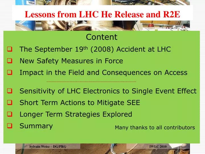
Lessons from LHC He Release and R2E. Splice joining the bus-bar of d ipole main circuit. Content The September 19 th (2008) Accident at LHC New Safety M easures in Force Impact in the Field and Consequences on Access ----------------------------------------------------------------------

E N D
Lessonsfrom LHC He Release and R2E Splice joining the bus-bar of dipole main circuit • Content • The September 19th (2008) Accident at LHC • New Safety Measures in Force • Impact in the Field and Consequences on Access • ---------------------------------------------------------------------- • Sensitivity of LHC Electronics to Single Event Effect • Short Term Actions to Mitigate SEE • Longer Term Strategies Explored • Summary Many thanks to all contributors Sylvain Weisz - BFSP Sylvain Weisz – DG/PRG IWLC 2010
Consequences of September 19th(2008) event in sector 3-4 of the LHC At the faulty connection Collateral damages due to pressure rise 2
Oxygen content in the tunnel (sensors on the ceiling) 12h00 16h48 R. Nunes
~ 10 GJ stored in magnetic field (154 dipoles in series) Circuit inductance =15 Henrys ( discharge =100s) LHC quench protection • when one magnet quenches, quench heaters are fired for this magnet • current in quenched magnet decays in about 200 ms • the current in all other magnets flows through the bypass diode that can stand the current for about 100-200 seconds; resistors are switched in series Power Converter resistors for energy extraction Magnet i Magnet 1 Magnet 2 Magnet 154 bypass diode R. Schmidt
2 Working Groups to analyse the 19/09/2008 event « Task Force » Mandate of the Task Force on the Analysis of the 19 September 2008 Incident Establish the sequence of facts, based on experimental measurements before incident, observations after incident and timing Analyse and explain the development of events, in relation with design assumptions, manufacturing & test data and risk analyses performed Recommend preventive and corrective actions for Sector 3-4 and others Mandate of the Task Force on Safety of Personnel in the LHC underground Establish the sequence of facts related to Safety of Personnel, based on AL3 data and FB emergency intervention records Analyse the LHC underground environmental conditions with respect to Safety of Personnel and explain their development in relation with original risk analyses (incl. Tests) performed Recommend preventive and corrective actions for the Safety of Personnel in the LHC underground
Recommandations of the Task Force on Safety of Personnel in the LHC underground • All efforts have to be made to limit an incidental helium release and the resulting overpressure • Any incidental helium release shall be confined to the ventilation sector where it occurs • This confinement must be carried out in combination with a controlled release of overpressure to the surface • No access shall be allowed to any ventilation sector of the LHC in which a large helium release has a non-negligible probability to occur. A ventilation sector is defined as the area directly affected by the overpressure resulting from the helium release. A large helium release is defined as being at least of the same order of magnitude as the release of 19th September 2008 accident.
Separation of the ventilation sectors – Experimental areas Interface between LHC and Detectors on beam line Interface with survey galleries Interface between detector caverns and machine areas Interface between experimental service caverns and machine (Pt5 only)
Sealing of the Experimental Areas(part 1) 1) Along the beam line Sealing around the TAS - ATLAS case built for 110mb (expect <32mb), Tmin 200K, compatible with ±15mm adjustment Interfaces with survey galleries ATLAS: UPS caps on survey ducts and doors built for 110mb (expect <32mb) Tmin200K fire resistant
Sealing of the Experimental Areas(part 2) 3) Interface between experimental cavern and service areas of the LHC machine ATLAS: fire (T90) and pressure resistant doors between US15 and UX15 (certified 40mb, expect <11mb) + sealing of all passages of Pipes and cable trays, spacing between shielding blocs. Use rock wool and Promafoam (fire resistant), re-enforcement
Helium release to surface – MCI 40kg/sec Helium release shafts
Helium release to surface Principle is to limit pressure rise in the tunnel • Sector1-2: • UJ14 closed-PM15-UJ16 open (TI18-PM18 blocked) (TI2 blocked) UL24 open-PM25-UL26 closed • Sectors 2-3 & 3-4: • UL24 closed-PM25-UL26 open (UJ32 « saloon door ») (UP33 blocked) UL44 open-PM45-UL46 closed • Sectors 4-5 & 5-6: • UL44 closed-PM45-UL46 open (UL55 « saloon door ») UL64 open-PM65-UL66 closed • Sectors 6-7 & 7-8: • UL64 closed-PM65-UL66 open (UJ76 « saloon door ») UL84 open-PM85-UL86 closed • Sector 8-1: • UL84 closed-PM85-UL86 open (TI8 blocked) (TI12 blocked) UJ14 open-PM15-UJ16 closed
Controlled Helium release – Ventilation doors Relief valve type of doors, in UJ14/16,UL24/26,UL44/46,UL64/66 & UL84/86 Door re-enforced, opens with 5mb overpressure from adjacent sector and stands 30mb from US side. Door positions monitored from CCC Deformation of re-enforced door: 30mb 7,4mm max. 13
Access matrix for the LHC undergroundNew access restrictions when main magnets are (or could be) powered Access conditions in LHC are documented in EDMS N°1010617 Magali Gruwe Use of US and PM shafts to evacuate He flow comdemn access to adjacent sector. In case of sectors linked with saloon doors (6/8), ~half of LHC is closed … Example of restriction when powering sector 4-5
Still to do … Sealing of LHC service areas Essentially a ventilation issue, will become a RP constraint at high intensity/luminosity Need to seal all ducts Generic case: Pt 2 Need to re-install ventilation doors in UP27 and UJ27 Re-enforced ventilation door, acts as relief valve 15
Situation15 seconds after opening of the safety valve: oxygen content (7m upstream) – temperature (7m downstream) Still to do … Safety during short access • Liquid He is transferred into surface storage tanks during x-mass breaks and shut-downs, but remains in the cryostat during short access • MCI without powering of main circuits can lead to a 1kg/s leak Fluid Dynamic simulationof a 1kg/s leak Lazlo Daroczy • Real hazard if present close to the valve • “No stay area” marks painted on the floor • Need improvement (Ex. early warning) Head level
Part 2 R2E - Single Event effects • Soft Errors (recoverable) • Single Event Upset (SEU) • Multiple Bit Upset (MBU) • Single Event Transient (SET) • Single Event functional Interrupt (SEFI) • Hard Errors (non recoverable) • Single Event Latch-up (SEL) • Single Event Gate Rupture (SEGR) • Single Event Burn-out (SEB) [Photos R. de Olivera EN/ICE]
A Few Numbers (xSections) • PLC-S7-200, Profibus (CV): 5.1x10⁻⁷ cm2 • 24V DC Power Supply (CV): 3.6x10⁻⁹ cm2 • PLC-S7-300 (CV): 3.0x10⁻⁸ cm2 • PLC-Schneider (CV): 2.8x10⁻⁷ cm2 (dominated by PS?) • WIC Rack 2.0x10⁻⁷cm2PLC S7-300 + FM352-5 Siemens: • Fire Detectors ASD: 5.9x10⁻⁹ cm2 • Ethernet Switch: 3.8x10⁻⁸cm2 • … ~1000 failures in a nominal year in UJ14/16 Other equipment: former test results, similar equipment, 10-7cm2 or lower! Uncertainty: up to one order of magnitude (but both directions!)
Critical Area Overview Markus Brugger Collimation Area(high losses possible at an early stage) High-Luminosity Experiments(UJs, RRs, possibly UPS) LHC Tunnel Electronics LHCb: reaches early significant radiation levels Injection & Adjacent Areas: losses on collimators and dumps on TED
Summary Of Areas Markus Brugger Point 7
Possible Strategies Mitigation Options Short term Longer term t • OTHER • SHIELDING • RELOCATION • CIVIL ENGINEERING • SEE-TOL DESIGN • RELOCATION
Layout of Point 7 Equipment sensitive to SEE can be found in UJ76 and in RR73/77
Point 7: status of relocation & shielding Strategy for SEE mitigation is described in EDMS # 977085: • Prepare space for relocation in TZ76 • Enlargement over 130 m done • Relocate in TZ76 what can be moved: • UPS and Network equipment were identified 1st priority done • Power converters are next preparation (cable routing and cooling) done • Remaining equipment of 1st floor of UJ76 slots assigned in TZ76 (thanks to ICL – J.P Corso & A.Tursun) • Shield what cannot be moved: • Safe room in UJ76 40 cm of iron in place on the LHC tunnel side • RR73 and RR77 40 cm of iron and movable chicane in place Insure QPS powering Potential drastic accident
Relocation of the UPS Before 2009 in UJ76 Now in TZ76
Summary Of Areas Markus Brugger UJ14/16/56: relocation study ongoing RRs: no space for relocation Point 7
RR caverns with potential radiation concerns for underground electronics RR57 RR53 RR73 RR77 RR17 RR13
1) New shafts & caverns to re-locate equipment underground John Osborne • Traditional shaft excavation techniques with 5m diameter shaft • Majority of CE work executed during machine operation • Noise / dust nuisance during CE works less of a problem • Risk associated with shafts passing through moraines • Risk to LHC due to vibration still to be assessed New Shaft ∅5m Existing LHC tunnel Existing RR New Access ∅3m Existing LHC tunnel New cavern ∅7m
Point 1 area – Google picture & Tunnels Emprise CERN 200m2 200m2
Point 5 area – Google picture & Tunnels 200m2 200m2 Emprise CERN
New Shafts and Caverns at Pt1&5: Cost and Schedule 23 months for CE works Lead time for construction work to start approx. 18months John Osborne GS-SEM
2) Develop SEE Tolerant LHC Power Converters • Overview of unknown or critical Items UNKNOWN VS RADIATION KNOWN or LOW RISKSAFE VS RADIATION LHC4-6-8kA-08V LHC600A-10V LHC120A-10V Yves Thurel / CERN 31
SEE Tolerant PC Project Development time • LHC Project Typical Development times StandardvsRad-Tol • Reducing Project duration can only be done reducing the design duration • Less design time = Higher risk of producing sensitive converter coherence??? Specif Standard Design Production + Reception Tests Install 1-year 2-years 2-years 6-m 6-m 2.5-years +/- 6 months 1.5-year 4-m Specif. Replace. Rad-tolerant Design Component validation & tests Production + Reception Tests Install Total duration = 5-years +/- 6 months + commissionning 2010-08 2015-08 2016-01 Yves Thurel / CERN 32
3) Relocation with Supra-Conducting Links Amalia Ballarino • Assumptions for the present study: • At P1 and P5 the preferred solution is the re-location of the LHC power converters in surface building . Priority is given to the RRs. • At P7 there is the possibility of a re-location in TZ76. Vertical link Horizontal link (Already done at Pt3 with Nb-Ti at 4.5K, L>400m) A. Ballarino R2E-Workshop, 10 June 2010
Vertical SC Power Links Room temperature Cryogenic environment (4.5 K LHe in the DFBs) Cold powering system: 1) Current leads in a distribution cryostat (near the power converters); 2) Vertical electrical transfer (link); 3) Horizontal electrical transfer (link); 4) Cryogenic fluid supply and control; 5) Interconnection to the magnets bus system; 6) Protection of link and current leads. Tunnel A. Ballarino RAD2-Workshop, 10 June 2010
Configuration of superconducting link 220 mm He Vacuum insulation plus MLI He MgB2 strand Thermal shield Cu stabilizer Superconducting 200 kA MgB2 multi-circuit assembly 100 electrically insulated cables 120 A, 600 A and 7000 A A. Ballarino R2E-Workshop, 10 June 2010
Superconducting MgB2 multi-circuit cables 1.1 mm MgB2 wire • Superconducting fully transposed and stabilized cables with a total current capability of • 120 kA were already assembled at CERN last year. • Sub-cables were tested at CERN at currents of up to 18 kA (@ 4.5 K and in self-field) A. Ballarino R2E-Workshop, 10 June 2010
Conductors for the superconducting link Nb-Ti → Tmax ≤ 7 K (Tc = 9 K) MgB2 → Tmax ≤ 20-25 K (Tc = 39 K) Bi-2223 or Y-123 → Tmax ≤ 77 K (Tc > 90 K) Temperature margin • Temperature margin: • Capability of adsorbing higher heat loads; • Increased stability of the superconductor (lower sensitivity to thermal or mechanical disturbances). MgB2 YBCO 123 BSCCO 2223 1.1 mm 4 mm A. Ballarino R2E-Workshop, 10 June 2010
3) Drill vertical boring from new surface building to re-locate equipment Drilling ∅400mm Existing LHC tunnel Existing RR Existing LHC tunnel
Relatively quick CE technique • Only possible for maximum 40cm internal diameter tube down to RR’s, is this sufficient ? • Risk associated with core this deep eg boulders in moraines, tolerances • Building permit required for surface buildings • Could envisage horizontal trenches to convey the SC power links into the existing surface buildings at Pt 1 & 5 (+200m of link each time)
Vertical borings and new surface buildings at Pt1&5: Cost and Schedule 12 months for CE works Lead time for construction work to start approx. 18months John Osborne GS-SEM
Summary Helium release issues and Single Event Effects mitigation are totally different subjects, but the main and obvious lesson is the same: These problems need to be addressed at an early stage of the project, late fixing is difficult, very expensive, long to achieve and usually not fully satisfactory.