Next Generation High Speed Board-Level Interconnect Using Fixed-Load Drivers
10 likes | 136 Views
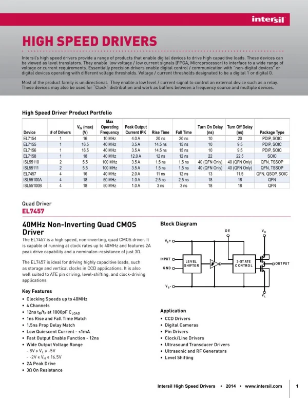
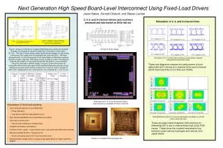
Figure 2: Example 4-channel Fixed-load current-steering driver (scaled up 6- and 8- channel versions implemented). Figure 1: Example of standard current-steering differential driver. Next Generation High Speed Board-Level Interconnect Using Fixed-Load Drivers.

Next Generation High Speed Board-Level Interconnect Using Fixed-Load Drivers
E N D
Presentation Transcript
Figure 2: Example 4-channel Fixed-load current-steering driver (scaled up 6- and 8- channel versions implemented) Figure 1: Example of standard current-steering differential driver Next Generation High Speed Board-Level Interconnect Using Fixed-Load Drivers Jason Bakos, Donald Chiarulli, and Steven Levitan 2, 4, 6, and 8-channel drivers and receivers designed and fabricated on SiGe fab run Simulation of 2, 4, and 8-channel links Figure 1 shows a schematic for a typical differential driver, where two physical channels are required to transmit a single bit of information (valid codes = {01,10}). This type of driver design yields significant advantages for high-speed interconnect, but suffers from an extremely low code rate (50%). We have designed driver circuits that possess all the advantages of differential signaling but with a higher code rate. With these circuits, exactly one half of the physical channels are pulled to a high potential and half are pulled to a low potential. Using the termination network shown in Figure 2, these drivers are fully compatible with existing high-speed LVDS standard differential receiver circuits (where one input on each receiver is tied to the “common” node). Number of valid “nCm” codewords for an n-channel driver are computed as: n!/(m!*(n-m)!). 8-channel driver design Simulation of 2, 4, and 8-channel drivers at termination network using 25cm transmission lines These eye-diagrams compare the performance of pure differential (2C1) drivers to 4-channel (4C2) and 8-channel (8C4) fixed-load links at 2.5 GHz and 10GHz. SiGe layout of 2, 4, 6, and 8-channel drivers and receivers on perimeter of 3mm x 3mm die • Advantages of fixed-load signaling: • Less total area required vs. pure differential • Power efficiency • Less silicon area and lower pad/wire count • High effective bandwidth (more information per symbol) • Low noise in driver circuit • Use of current steering for constant load • Coupled transmission line behavior • Common-mode / supply - noise rejection due to use of pair-wise differential receivers • Minimal overhead for ECC / channel control • Extra code words used for ECC and channel control • Reduced signal voltage swing vs. single-ended yields allows for higher switching speeds Static EM field solutions for various topologies and states on a PCB (cross-sectional view) These are static electromagnetic field solutions for differential (2C1) and 4-channel fixed-load (4C2) PCB traces. These show the coupled-transmission line behavior under various topologies and various nCm signal states. Images of completed SiGe packaged die