Download
1 / 16
160 likes | 276 Views
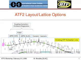
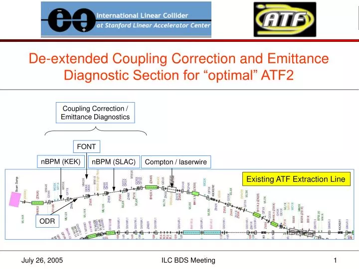
De-extended Coupling Correction and Emittance Diagnostic Section for “optimal” ATF2. Coupling Correction / Emittance Diagnostics. FONT. nBPM (KEK). nBPM (SLAC). Compton / laserwire. Existing ATF Extraction Line. ODR. wall.

E N D
De-extended Coupling Correction and Emittance Diagnostic Section for “optimal” ATF2 Coupling Correction / Emittance Diagnostics FONT nBPM (KEK) nBPM (SLAC) Compton / laserwire Existing ATF Extraction Line ODR ILC BDS Meeting
wall Insufficient space in previous design for post-IP diagnostics, beam-photon separation, dump, and shielding … need to shorten system by ≈ 5 m 5 m ILC BDS Meeting
EXT Diagnostic Section (optimal2) SQ SQ SQ SQ 2.0 2.0 2.0 2.0 2.0 2.0 2.0 2.0 2.0 1.3 1.3 1.3 1.3 WS WS WS WS WS – x – y 90° 90° 180° 90° 90° 90° 33° 57° 57° 33° 33° 57° 57° 33° 59.2 8.3 108.0 4.5 59.2 8.3 108.0 4.5 59.2 8.3 σ (μm) ILC BDS Meeting
SQ SQ SQ SQ WS WS WS WS WS 1.0 1.0 1.0 0.7 0.7 0.7 0.7 1.0 1.7 1.0 3.0 3.0 3.0 – x – y 90° 90° 180° 90° 90° 90° 55° 25° 41° 31° 31° 41° 26° 26° 34.1 8.6 136.3 6.2 80.4 10.5 136.3 6.2 80.4 10.5 σ (μm) ΔL = -5.0 m (w.r.t. optimal2) ILC BDS Meeting
β*x,y = 4,0.1 mm 30 cm offset ILC BDS Meeting
new quadrupole (between QF3X and BH1X.3) ILC BDS Meeting
14.13 m (IP to wall) Assembly Hall ILC BDS Meeting
Layout / survey • as-installed survey coordinates of existing EXT magnets come from a previous incarnation of the SAD input • magnet core lengths were used for effective lengths • SAD “COORD” elements (which model beams going off-axis through quadrupoles) were correct for vintage QM6R/QM7R strengths • Woodley’s MAD deck based on 1999 SAD input from T. Okugi • corrected effective lengths for magnets … bend angles not changed • “DRLBW44” strengths for QM6R and QM7R • SAD “COORD” elements not updated MAD SURVEY coordinates for existing EXT magnets were wrong at the centimeter level ILC BDS Meeting
Layout / survey (2) • MAD deck corrected to match as-installed survey coordinates of existing EXT magnets (quads and bends) • effective lengths of QM6R, QM7R, and bends set to their core lengths • off-axis quadrupoles QM6R and QM7R modeled as bends with gradients … bend angles adjusted to emulate effects of SAD “COORD” elements • drift spaces between magnets adjusted accordingly MAD SURVEY coordinates for existing EXT magnets now agree with as-installed SAD survey coordinates1 at the micrometer level 1See S. Kuroda’s SAD survey output file: ff3.5.1_disp_g.txt ILC BDS Meeting
SAD/MAD Geometry Comparison (ff3.5.1_disp_g.txt vs “optimal3”) Name s (SAD) S (MAD) Gx (SAD) Z (MAD) Gy (SAD) X (MAD) Chi1(SAD) YAW (MAD) ---- --------- --------- --------- --------- --------- --------- --------- --------- KE1X 0.250000 0.250000 0.000312 0.000312 0.250000 0.250000 0.143239 0.143239 BS1X 3.700071 3.700077 0.025150 0.025150 3.699973 3.699973 0.868459 0.868459 BS2X 4.600071 4.600077 0.056730 0.056730 4.599332 4.599332 3.801402 3.801402 BS3X 5.700071 5.700077 0.192062 0.192062 5.689944 5.689944 12.664068 12.664068 QD1X 7.290071 7.290077 0.692058 0.692058 7.198357 7.198357 19.396953 19.396953 BH1X 8.080071 8.080077 0.971859 0.971859 7.936761 7.936761 24.754357 24.754357 QD2X 8.810071 8.810077 1.321633 1.321633 8.577118 8.577118 30.111760 30.111760 QF1X 9.635503 9.635509 1.735743 1.735743 9.291156 9.291156 30.111760 30.111760 BH2X 10.400070 10.400076 2.102860 2.102860 9.961415 9.961416 24.754357 24.754357 QF2X 11.969442 11.969448 2.641499 2.641499 11.434954 11.434954 19.396953 19.396953 QD3X 13.930070 13.930076 3.292645 3.292645 13.284298 13.284298 19.396953 19.396953 KE2X 15.850070 15.850076 3.930593 3.930592 15.095215 15.095216 19.540192 19.540192 QF3X 16.490070 16.490076 4.145865 4.145865 15.697924 15.697924 19.683432 19.683432 BH3X 17.980070 17.980076 4.629940 4.629940 17.106606 17.106606 14.326028 14.326028 QF4X 18.870070 18.870076 4.787053 4.787053 17.982236 17.982236 8.968625 8.968625 QD4X 19.530070 19.530076 4.889943 4.889943 18.634167 18.634167 8.968625 8.968625 QD5X 21.820070 21.820076 5.246939 5.246939 20.896169 20.896169 8.968625 8.968625 BH4X 23.189144 23.189150 5.407974 5.407974 22.253998 22.253998 0.019047 0.019047 QF5X 24.340144 24.340149 5.281695 5.281695 23.396503 23.396503 -8.930530 -8.930530 Note: Chi1 and YAW are degrees; everything else is meters ILC BDS Meeting
Continuing work • verify that sufficient space is now available for post-IP diagnostics and dump (radiation safety considerations) • can we can put < 10 μm diameter carbon wires in wire scanners? • TURTLE tracking … optimize system bandwidth and performance • revisit simulations of steering and dispersion/coupling correction with machine and diagnostics errors • document quad locations, strengths, and power supply configuration • update for ATF2 proposal document ILC BDS Meeting