Download

1 / 55
580 likes | 918 Views
ITU Regional Workshop on SMS4DC for English Speaking countries in Africa, Abuja, Nigeria , 20-31-May 2013. Propagation Models In SMS4DC. Prepared by : Eng.Yasir Mohammed Bashar Yasir_192@ntc.gov.sd. Radio propagation fundamentals.

E N D
ITU Regional Workshop on SMS4DC for English Speaking countries in Africa, Abuja, Nigeria , 20-31-May 2013
Propagation Models In SMS4DC Prepared by : Eng.Yasir Mohammed Bashar Yasir_192@ntc.gov.sd
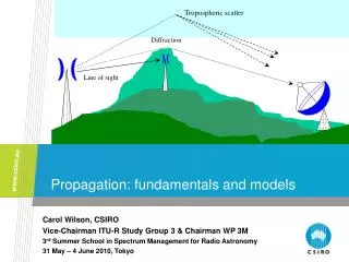
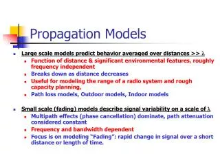
Radio propagation fundamentals Propagation is a term used to explain how radio waves behave when they are transmitted, or are propagated from one point on the Earth to another. In free space, all electromagnetic waves (radio, light, X-rays, etc.) obey the inverse-square law which states that the power density of an electromagnetic wave is proportional to the inverse of the square of the distance from a point source Doubling the distance from a transmitter means that the power density of the radiated wave at that new location is reduced to one-quarter of its previous value.
Types of Communications Point to point communication: Communication provided by a link, for example, radio-relay link between two stations located at specified fixed points
Point to multipoint communication Communication provided by links, for example, radio-relay links between single station located at specified fixed point and a number of stations located at specified fixed points.
Point to Area communication Communication provided by links between a station located at a specified fixed point and any number of stations located at non-specified points in a given area which is the coverage area of the station located at the fixed point.
P.370 VHF and UHF propagation curves for the frequency range 30 - 1000 MHz Propagation Models In SMS4DC P.452 Prediction procedure for the evaluation of microwave interference between stations on the surface of the Earth at frequencies above about 0.7 GHz P.525 Calculation of free space attenuation P.526 Propagation by diffraction P.529 Prediction methods for the terrestrial land mobile service in the VHF and UHF bands P.530 Propagation data and prediction methods required for the design of terrestrial line-of-sight systems P.618 Propagation data and prediction methods required for the design of Earth-space telecommunication systems P.1546 Method for point-to-area predictions for terrestrial services in the frequency range 30 MHz to 3 000 MHz
Some Useful Concepts for Propagation models Fading :Fluctuation of signal level with respect to stable condition for number of reasons. Path profile: A vertical cut of terrain along propagation path between transmitter and receiver NFD: Net Filter Discrimination (NFD) expresses the reduction (in dB) of the interference power if the transmitter and receiver frequencies are different Polarization: The Locus of Electric field vector fluctuation
Propagation Effects Diffraction fading due to obstruction of the path; Attenuation due to atmospheric gases; Fading due to atmospheric multipath or beam spreading (commonly referred to as defocusing) associated with abnormal refractive layers; Fading due to multipath arising from surface reflection; Attenuation due to precipitation or solid particles in the atmosphere; Variation of the angle-of-arrival at the receiver terminal and angle-of-launch at the transmitter terminal due to refraction; Reduction in cross-polarization discrimination (XPD) in multipath or precipitation conditions; Signal distortion due to frequency selective fading and delay during multipath propagation.. Attenuation due to sand and dust storms Multipath Fading Cross-polarization discrimination
ITU-R P.370 • Intended for prediction of field strength for the broadcasting service for the frequency range 30 to 1 000 MHz and for the distance range up to 1 000 km Replaced by P.1546 but still used in some bilateral agreements Input parameters: % Time (range 1 – 50 %): typical 1% for interference contour 50 % for coverage contour % Locations (range 1-99 %): typical coverage contour 99 % interference contour 50 % • Δh defines the degree of terrain irregularity; for broadcasting services it is applied in the range 10 km to 50 km from the transmitter. Typical value = 50 m. • Contour value: appropriate to service type e.g. VHF land mobile fsmin =12dBμV/m • Land/Sea discrimination: if checked will apply correction for % sea/land path
Field strength contour using ITU-R P.370 Select P.370 and Field strength Contour from Propagation Models menu Select station for contour calculation
P.370 Input parameters % Time: (1 – 50 %) % Location: (1 – 99 %) Effective radius of the Earth: (k=4/3) System: Analogue/Digital Environment: see inset Land/Sea discrimination Receiver height Delta H Contour value
P.452: Prediction procedure for the evaluation of microwaveinterference between stations on the surface of the Earth atfrequencies above about 0.7 GHz • –N0 (N-units), the sea-level surface refractivity, is used only by the troposcatter model as a measure of location variability of the troposcatter mechanism. • – Delta_N (N-units/km), the average radio-refractive index lapse-rate through the lowest 1 km of the atmosphere, provides the data upon which the appropriate effective Earth radius can be calculated for path profile and diffraction obstacle analysis. • – Beta_e(%), the time percentage for which refractive index lapse-rates exceeding 100 N-units/km can be expected in the first 100 m of the lower atmosphere,
P.525 Calculation of Free Space Attenuation 1 • Point-to-area links: If there is a transmitter serving several randomly-distributed receivers (broadcasting, mobile service), the field is calculated at a point located at some appropriate distance from the transmitter by the expression: where: e : r.m.s. field strength (V/m) p : equivalent isotropically radiated power (e.i.r.p.) of the transmitter in the direction of the point in d : distance from the transmitter to the point in question (m).
P.525 Calculation of Free Space Attenuation • Point-to-point links:With a point-to-point link it is preferable to calculate the free-space attenuation between isotropic antennas, also known as the free-space basic transmission loss (symbols: Lbf or A0), as follows: where: Lbf : free-space basic transmission loss (dB) d : distance λ : wavelength
P.1546 • This Recommendation describes a method for point-to-area radio propagation predictions for terrestrial services in the frequency range 30 MHz to 3 000 MHz • It is intended for use on tropospheric radio circuits over land paths, sea paths and/or mixed land-sea paths between 1‑1 000 km length for effective transmitting antenna heights less than 3 000 m
Step 3 Establish a fix stations A using and set the frequency to 890 MHz
Step 5,6 do the same steps as in 3 and 4 to Establish a fix stations B and set the frequency to 890 MHz
Step 4 Press assign antenna button to chooseantenna “ant_ALE8603_806.ant”
Step 7 Open the administrative part from“Database->licensing”
Step 8: Select “Anonymous Station” and find stationB, open Antenna Information Table of Station B
Step 9 : Push modify button and change the field“class of antenna” from T to C and push save button
Step 10: Find Station A and go to the Frequency taband press “Add Receiver” and follow the dialogbox (Choose station B from table under POINT, andthen close the admin window
Step 13 Open menu “Propagation Model” and select Link item under the ITU-R P.370 propagation model