Download
1 / 11
110 likes | 257 Views
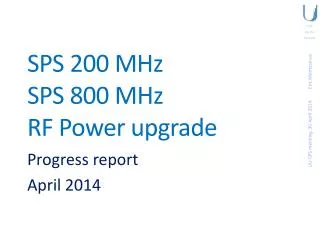
SPS 200 MHz RF Power limits. 02 July 2014. SPS 200 MHz power. Main reasons for Power limitation Amplifier Transmission Line Fundamental Power Coupler Cavity Terminating Load. Amplifier. Transmission Line. Load. FPC. FPC. Cavity. Transmission Lines. No WG available at 200 MHz

E N D
SPS 200 MHzRF Power limits LIU-SPS meeting, 02 July 2014 02 July 2014
SPS 200 MHz power Main reasons for Power limitation • Amplifier • Transmission Line • Fundamental Power Coupler • Cavity • Terminating Load Amplifier Transmission Line LIU-SPS meeting, 02 July 2014 Load FPC FPC Cavity
Transmission Lines No WG available at 200 MHz Maximum size with coaxial transmission lines is 350 mm (14”) Lines Power limitation is mainly due to inner line overheating Absolute maximum ratings: • 870 kW average • Ambient temp 40 ⁰C • Inner temp 120 ⁰C • In operation 750 kW
Pamplifier vs Pcavity With 150 to 180 meters of transmission lines from BAF3 surface building to LSS3, losses in transmission lines are optimistically estimated to -0.5 dB, i.e. + 12 % of power on the amplifier side ! 1.6 MW to be delivered to the cavity corresponds to 1.8 MW to be provided by the amplifiers ! + 12 %
Needed power LIU-SPS meeting, 02 July 2014
Transmission Lines How to increase the Maximum ratings Pressurization of the line • If pressure > 2.8 bars EU pressure equipment directive has to be applied • Inner temp 170 ⁰C, decrease lifetime of contacts Pressurization and decrease outer temp • Water cooling of the outer conductor • Outer temp 30 ⁰C instead of 40 ⁰C • With 2.8 bars, 120 ⁰C
Transmission Lines How to increase the Maximum ratings Cooling the inner conductor • Air • Inlet temp must be 20 ⁰C (lower than the SPS temp) • Flow > 3500l/min • Some plain ceramics lead into several circuits Double the number of lines • Size of the tunnel is given • Tunnel is quite full LSS3- LSS3+
Transmission Lines http://cds.cern.ch/video/CERN-VIDEORUSH-2014-033-001 The goal is to find a way to sustain 1.8 MW at the amplifier side in order to deliver 1.6 MW to the cavity Still working on it, more to come soon LIU-SPS meeting, 02 July 2014
FPC + Cavity Current FPC • tested up to 800 kW peak • Too long Design • a more compact one • 1 MW peak Connection to the cavity has to be improved LIU-SPS meeting, 02 July 2014
Amplifier Whatever the technical solution selected, more power will ‘only’ be a question of cost LIU-SPS meeting, 02 July 2014