Quadrant diode configuration
This comprehensive text explores the comparison between 'X' and '+' configurations of quadrant diodes, focusing on relative sensitivity, error signal couplings, misalignment sensitivity, and normalized asymmetry fluctuation. It delves into the specifications, functions, and practical considerations of ISYS Quadrants PHD, providing insights into the performance and potential enhancements of quadrant photodiodes. The discussion also raises questions regarding extending the LA standard for ISYS quadrants, the use of different quadrant diodes for monitoring purposes, and the implementation of a fast quadrant centering system for beam stabilization. Through detailed analysis and theoretical considerations, this text offers valuable information for optimizing quadrant diode configurations in various applications.

Quadrant diode configuration
E N D
Presentation Transcript
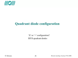
Quadrant diode configuration • ‘X’ or ‘+’ configuration? • ISYS quadrant diodes
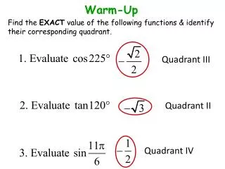
Comparison ‘X’ and ‘+’ configuration • Relative sensitivity of X configuration • Virgo QD’s are used in X configuration • Same signal-to-noise-ratio as + config. • Couplings • Horizontal/vertical error signal couplings • X config: couplings for h+v miscentering • Misalignment sensitivity • Strong horizontal or vertical misalignment: • X config may give no error signal • Conclusion • For new QD front ends • “+” configuration desirable vs.
Simulation h/v couplings • Simulation of horizontal/vertical coupling • Normalized asymmetry fluctuates − 0.5 … + 0.5 (C7) • ‘X’ config: 4 % coupling Θx − Θy ‘+’ config: none Q81 (8 hours) dh = dv = 0.3 Normalized asymmetry Power as seen by QD (horizontal) C7 Normalized asymmetry
ISYS quadrant diodes • Overview
ISYS Quadrants PHD (IMC, RFC) (Preliminary results) Quadrant photodiode specifications - Centronic QD40-4x, silicon photodiode (EG&G YAG 444-4) - 7.98mm diam, 200microns gap, 0.4 A/W (11.4 mm, 0.45 A/W) - 120V bias (IMC & RFC) (180 V) - 10mA peak current (3 mA) - “+” geometrical configuration (“X” configuration) Quadrant “box” specs. - 6 MHz & 22 MHz, demodulation done onboard (RFC, IMC respectively) - IMC & RFC: involved in servo-loops - vertic/horiz error signals (AC & DC) provided onboard, BNC connectors (unipolar) - R_ac: 50 kohm - 4quadrants, shot noise limited for 16 mA, should be 0.6mA, (need TBC and check reason for extra noise) (in that case, S/N would be equivalent to Frascati quadrants) Frascati QD’s
ISYS Quadrants PHD (IMC, RFC, PMC, SL) Centering electronics
ISYS Quadrant PHD (IMC, RFC, PMC, SL) • Discussion • we can work shot noise limited with present ISYS quadrants • Question : • Is it worth to extend LA standard for ISYS quadrants (2*4)? • Main advantage: standardization • Price to pay: • - Extra demodulation boards • - Extra cabling • - Swap translation stages • - rearrange optical setup? (VIRGO quadrant box larger) • What about QDs for monitoring SL & PMC (nearly same as IMC & RFC) (14 MHz)? • What about DC QDs (BMS, MC end mirror transmission)? • at present: EGO is to provide those QDs (UDT photodiodes already bought), • use temporarily PMC QDs (for BMS), and Nice QD for MC mirror
LA electronics TStage driver Demodulator board (2 channel) Phase shifter (2 channel) QD front end
Quadrant photodiode • type EG&G YAG 444 • sensitivity = 0.45 A/W • DC power = 3 mWmax • transimpedance = 2 k • Bias voltage = 180 V
QD electronics phase shifter demodulator Quadrant diode box
Scheme of LA electronics Low-pass filter AC: Gain 200 diff. sig. QD box Shot noise VME non-diff.sig. DC: Gain 1 Preamp. noise ADC noise Non-optimal treatment of DC signals dominated by ADC noise (but were not foreseen as error signals)
Noise measurements after demodulator demodulator gain quadrant diode AC output Theoretical shot noise M. Mantovani
Influence of QD power Can gain ~ factor 10 by increasing QD powers
Fast quadrant centering system • Couplings • Coupling with longitudinal error signals • Horizontal/vertical error signals are coupled if h & v miscentering • Coupling with waist mismatch • Coupling with longitudinal noise • Better rms centering required • See G. Vajente’s talk (Napoli 03/10/2005) • Bad mirror motion reconstruction • Not understood • Fast QD centering system could remain ON all time • Control signal would be used for beam stabilization • Present system too noisy
Requirements for centering With the present centering configuration (activates every few minutes) RMS change of a factor of 4 Extrapolating from these measurements… Taking a reasonable range around the “minimum”, the maximum DC asymmetry must be less than 0.1 Even with the best centering rate now possible (every 4-5 seconds) we can’t reach this precision.