Quest Web-Browser Interface
Quest Web-Browser Interface. Home Page.

Quest Web-Browser Interface
E N D
Presentation Transcript
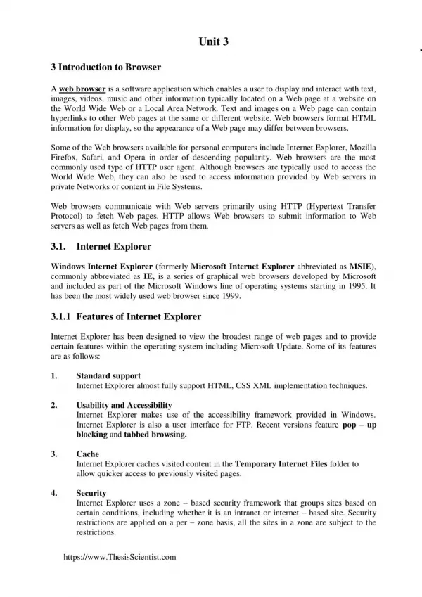
Home Page This is the Home Page of the Quest Browser Interface. This page will show the site information, and any active alarms. The hyperlinks on the left of the page will allow you to navigate through the interface. The Network Card firmware is displayed below the Contact hyperlink.
Input Page This page will provide all information about the sensors attached to the Telsec Unit. There are two types of inputs: analog & digital. The digital inputs will have a value of ‘ON’ or ‘OFF’. The analog inputs will provide information within a scale, like temperatures.
Output Page This page will provide information about the equipment being controlled by the Telsec. There are 2 types of control signals, digital outputs are signals with ‘ON’ and ‘OFF’ . Analog signals are control signals within a controlled range, like making a damper 75% open. The bypass hyperlinks will allow you to change the state of a relay at the push of a button.
Setpoint Page This page contains values that can be modified to affect the operation of the Telsec. These values are internal to the unit and are not affected by sensors. Examples of these setpoints are controlled temperatures, time limits, and alarming thresholds.
Alarms Page The active alarms will be listed here. The Alarm History hyperlink will allow you to view the last 99 alarm events with a snapshot of the time and alarming value. Clearing alarms are separate events from Active alarming events.
RTUs Page All RTUs will be listed here. The type is the method of controlling the HVAC unit, these will depend upon the type of HVAC unit. The zone temperature will control the RTU. The setpoint is the point at which the unit will attempt to cool. This value will update automatically based upon the adjustable slide. The Zone ADJ value shows the current location of the wall slide switch. (continued on next slide)
RTUs Page The Heat differential is the value maintained between heating & cooling, the setpoint minus the heat differential will give you the temperature that the heat will come on. The supply temperature is the temperature of the air coming out of the HVAC unit. There are 2 digital alarms, one indicates that the fan is running, the other indicates that when the air filter is clogged. The High and Low Alarm values will indicate if the zone temperature has crossed the alarming threshold. The information on this page will remain until the RTU controller updates the information.
Bus Page This page will show the current communication between the Telsec and remote boards. These remote boards would include RTU controllers as well as Expansion Input & Relay boards.
Schedules Page This page will provide access to the control schedules. These schedules will determine occupied time and alarming times based upon programming. There is a Date Schedule which will allow for exceptions to standard control schedules.
Logging Page This page will create a graphical representation of up to 4 inputs, or 1 RTU controller at a time. The time period selected will determine the time period between the data points. This page will also allow you to download a text file with the requested logging data.
Set Clock Page This page will allow you to select the local time and date for the unit. This information will affect the time-stamps for data gathered, and it will be used in the control schedules that are programmed in the unit.
Alarm Dispatch Page This page will determine how the alarms created by the Telsec will be remotely dispatched. Depending upon the server that the alarming information will be sent to, this information can be sent to a dynamic name or to a static IP address. Alarm filtering can also be revised at this page to determine the types of alarms sent. These alarms can be sent to up to 4 different addresses, these alarms can be concurrently dispatched as required from the customers equipment.
Web Server Page This page will allow you to change the settings of the Telsec. The DHCP will allow the unit to dynamically ‘find’ an IP address that the Router will assign. If DHCP is not selected, the unit will be statically assigned an IP address. The access information and site information can be modified here.
Access Control Page Door access information is stored here. You can review door access history, view accepted key cards, and open a door remotely.
Command Line Link The Command Line link will launch an application chooser, select the Telnet application that you would like to use to interface with the Telsec.