
Wireless Central Control Unit DCNW Tech PT CCE - Features and Specifications
E N D
Presentation Transcript
Wireless Central Control Unit DCNW Tech PT CCE
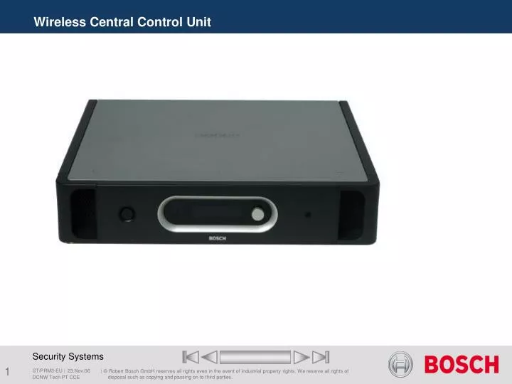
2 1 3 4 Wireless Central Control Unit • 1Mains on/off switch A switch to switch on and off the CCU. • 2Menu display A 2x16 character LCD display gives information about the CCU. It is also used to configure the system. • 3Menu button A turn-and-push button to operate the menu in combination with the display. • 4Monitoring headphones output A 3.5 mm jack socket to connect headphones for audio monitoring purposes. I&U Instructions DCNW Tech PT CCE
6 7 5 10 11 12 14 8 9 12 11 13 Wireless Central Control Unit • 5RS232 ports 2 x 9-pin Sub-D connector for: • Open interface (for remote control functions) • Terminal (service diagnostics) • Full protocol (direct PC control) • Camera Control • 6Mains inlet A socket to connect the CCU to the mains. • 7Ground A connection to mechanically ground the CCU. I&U Instructions DCNW Tech PT CCE
10 11 12 14 8 9 12 11 13 Wireless Central Control Unit • 8Optical network Two sockets to connect the CCU to the optical network for connecting other optical devices to the system. Each socket has a red LED that indicates overload situations. Note: Even if only one of the optical network sockets has a power overload, both overload LEDs will be activated and the power will be removed from both sockets. • 9DCN sockets Two sockets to connect the DCN Next Generation units to the CCU. Each socket can supply 65 Watt and has a red LED that indicates overload situations. • 10Fault contact A potential-free change-over relay contact that indicates the correct operation of the CCU. I&U Instructions DCNW Tech PT CCE
10 11 12 14 8 9 12 11 13 • 11Audio input Two audio inputs to insert analogue audio signals that originate from external audio sources into the system.` • 12 Audio output Two audio outputs to extract analogue audio signals from the system. Wireless Central Control Unit I&U Instructions DCNW Tech PT CCE
Wireless Central Control Unit 10 11 12 14 8 9 12 11 13 • 13Voltage selector to select the local mains voltage 115/230. • 14Fuse holder with a fuse that protects the power supply of the CCU. I&U Instructions DCNW Tech PT CCE
Product Technology End of section DCNW Tech PT CCE