Download
1 / 65
710 likes | 1.08k Views
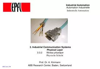
Industrial Automation Automation Industrielle Industrielle Automation. 3.3.2. 3. Industrial Communication Systems Physical Layer 3.3.2 Niveau physique Physische Schicht. Prof. Dr. H. Kirrmann. ABB Research Center, Baden, Switzerland. Physical Layer Outline. 1. Layering. 2. Topology.

E N D
Industrial AutomationAutomation IndustrielleIndustrielle Automation 3.3.2 3. Industrial Communication Systems Physical Layer 3.3.2 Niveau physique Physische Schicht Prof. Dr. H. Kirrmann ABB Research Center, Baden, Switzerland
Physical Layer Outline 1. Layering 2. Topology 3. Physical media 4. Electric Signal coupling 5. Optical Fibres 6. Modulation 7. Synchronization 8. Encoding 9. Repeaters
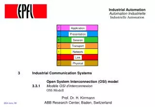
OSI Model - location of the physical level All services directly called by the end user Application 7 (Mail, File Transfer,...) Application Definition and conversion of the Presentation 6 protocols data formats (e.g. ASN 1) Management of connections Session 5 (e.g. ISO 8326) End-to-end flow control and error recovery Transport 4 (z.B. TP4, TCP) Routing, possibly segmenting Network 3 (e.g. IP, X25) Transport protocols Error detection, Flow control and error recovery, Link 2 medium access (e.g. HDLC) Coding, Modulation, Electrical and Physical 1 mechanical coupling (e.g. V24)
Subdivisions of the physical layer medium-independent signalling same for different media (e.g. coax, fibre, RS485) medium-dependent signalling applies to one media (e.g. optical fibres) Physical Layer electrical / optical specifications applies to one media type (e.g. 200µm optical fibres) mechanical specifications defines the mechanical interface (e.g. connector type and pin-out)
Concepts relevant to the physical layer Topology Ring, Bus, Point-to-point Mechanical Connector, Pin-out, Cable, Assembly Medium signals, transfer rate, levels Channels Half-duplex, full-duplex, broadcast Control Send, Receive, Collision Modulation Baseband, Carrier band, Broadband Coding/Decoding Binary, NRZ, Manchester,.. Synchronisation Bit, Character, Frame Flow Control Handshake Interface Binary bit, Collision detection [multiple access] Signal quality supervision, redundancy control
Example: RS-232 - Mechanical-Electrical Standard Originally developed for modem communication, now serial port in IBM-PCs Telephone Topology: lines DTE DCE DCE DTE Data Data 2 2 Terminal Terminal Equipment Equipment Terminal Data Communication Modem Computer Equipment (Modem) Cabling rules modem eliminator extension extension Tip: Do not use 2 terminal computer Modem cables, only Extension cable cable cables 2 3 7 Mechanical 1 25 transmitter receiver Electrical: +12V +3V "0" Space On "1" Mark Off -3V -12V
Physical Layer Outline 1. Layering 2. Topology 3. Physical media 4. Electric Signal coupling 5. Optical Fibers 6. Modulation 7. Synchronization 8. Encoding 9. Repeaters
Topology: Simplex, Half and Full Duplex Link (Point -To-Point) Full-duplex Examples: Sender/ Sender/ RS232 Receiver Receiver Half-duplex Examples: Sender/ Sender/ RS485 Receiver Receiver Bus (Half-Duplex, except when using Carrier Frequency over multiple bands) Terminator Examples: Ethernet, Profibus Ring (Half-Duplex, except double ring) Examples: SERCOS, Interbus-S consists of point-to-point links
Bus topologies party-line Terminator Terminator advantage: little wiring disadvantages: easy to disrupt, high attenuation and reflections, no fibres hub point-to-point star advantage: robust point-to-point links, can use fibres disadvantage: requires hub, more wiring radio free topology repeater a bus is a broadcast medium (delays come from propagation and repeaters)
Repeater 500m To connect a workstation of department A to the printer of department B, the cable becomes too long and the messages are corrupted. department A server workstations The repeater restores signal levels and synchronization. It introduces a signal delay of about 1..4 bits Ethernet repeater printer 500m server department B Physically, there is only one Ethernet carrying both department’s traffic, only one node may transmit at a time. Ethernet 500m
Bus: repeaters and hubs higher-level hub repeaters partyline partyline point-to-point link hubs assemble point-to-point links to form a broadcast medium (bus)
Party-line (bus) and star wiring d = average distance between devices wiring length = d • n, increases linearly with number of devices PLC d Up to 32 devices (more with repeaters) I/O I/O I/O I/O I/O party-line wiring is well adapted to the varying topography of control systems hub wiring length = d • n • n / 2 • 2 increases with square of number of devices PLC Up to 16 devices per hub does it fit into the wiring tray ? I/O I/O I/O I/O I/O star wiring may more than offset the advantage of field busses (reduced wiring) and leads to more concentration of I/O on the field devices.
Rings a ring consists only of point-to-point links Each node can interrupt the ring and introduce its own frames classical ring ring in floor wiring wiring cabinet The wiring amount is the same for a bus with hub or for a ring with wiring cabinet. Since rings use point-to-point links, they are well adapted to fibres
Physical Layer Outline 1. Layering 2. Topology 3. Physical media 4. Electric Signal coupling 5. Optical Fibres 6. Modulation 7. Synchronization 8. Encoding 9. Repeaters
twinax 8 0.9 0.2 3.5 very good Media (bandwidth x distance) Transfer rate (Mbit/s) Costs Electromagnetic (Fr/m) Compatibility 200m 700m 2000m optical fibres single mode 2058 516 207 5.5 very good multimode 196 49 20 6.5 very good plastic 1 0.5 - 6.5 very good coaxial cables 50 Ohm 20 8 1 1.2 good 75 Ohm TV 1/2" 12 2.5 1.0 2.2 good 93-100 Ohm 15 5 0.8 2.5 good twisted wire individually 2 0.35 0.15 .5 very good shielded (STP) good (crosstalk) group shielding (UTP) 1 0.3 0.1 1 regular (foreign) good (crosstalk) Telephone cable 0.2 0.1 0.05 0.2 bad (foreign) others Power line carrier 1 0.05 0.01 - very bad Radio 1 1 1 - bad Infrared 0.02 0 0 - good ultrasound 0.01 0 0 - bad the bandwidth x distance is an important quality factor of a medium
Physical Layer Outline 1. Layering 2. Topology 3. Physical media 4. Electric Signal coupling 5. Optical Fibres 6. Modulation 7. Synchronization 8. Encoding 9. Repeaters
Electrical: Transmission media Cost efficient wiring: twisted pair (without Zw = 50Ω ... 100Ω Coaxial cable core inflexible, costly, low losses 10 MHz..100 MHz dielectric shield screen Shielded twisted wire (Twinax) Zw = 85Ω..120Ω flexible, cheap, medium attenuation ~1 MHz..12 MHz Shield twisting compensates disturbances very cheap, sensible to perturbations Unshielded twisted wire Telephone Uncommitted wiring (e.g. powerline com.) very cheap, very high losses and disturbances, very low speed (~10 ..100 kbit/s) numerous branches, not terminated, except possibly at one place 1) Classical wiring technology, 2) Well understood by electricians in the field 3) Easy to configure in the field 4) Cheap (depends if debug costs are included) 1) low data rate 2) costly galvanic separation (transformer, optical) 3) sensible to disturbances 4) difficult to debug, find bad contacts 5) heavy
Electrical: Twisted wire pair characteristic impedance most used in industrial environment: 120 Ohm for bus, 150 Ohm for point-to-point. Standard from the telecommunication world: ISO/IEC 11801 Cat 5 (class D): 100 MHz, RJ 45 connector Cat 6 (class E): 200 MHz, RJ 45 connector Cat 7 (class F): 600 MHz, in development These are only for point-to-point links ! (no busses)
Electrical: What limits transmission distance ? Characteristic impedance Attenuation Linear resistance All parameters are frequency-dependent Linear capacitance Cross talk Common-mode Shield protection Attenuation: copper resistance, dielectric loss. Frequency dependent losses cause dispersion (edges wash-out): Signal reflection on discontinuities (branches, connectors) cause self-distortions
Consider in cables - characteristic impedance (Zw) (must match the source impedance) - attenuation (limits distance and number of repeaters) - bending radius ( layout of channels) - weight - fire-retardant isolation lumped line model L' L' L' L' R' R' R' R' C' C' C' C' G' G' G' G' specific inductance (H/m) specific resistance (/m) specific capacitance (F/m) specific conductance (S/m) L' Zw = C'
Electrical: Signal Coupling Types Resistive direct coupling driver on line without galvanic coupling collision possible when several transmitters active Wired-OR combination possible cheap as long as no galvanic separation is required (opto-coupler) good efficiency Inductive transformer-coupling galvanic separation good electromagnetic compatibility (filter) retro-action free good efficiency signal may not contain DC-components bandwidth limited Capacitive capacitor as coupler weak galvanic separation signal may not contain DC components cheap not efficient
Electrical: Resistive (direct) coupling Unipolar, unbalanced Bipolar, unbalanced + Us Coax Ru + Us Zw Zw Rd - Us Open Collector Ut Ut = 5 V (e.g.) (unbalanced) Terminator and Rt Rt Bus line, characteristic impedance = Zw Pull-up resistor wired-OR behaviour (“Low” wins over “High” Out In Out In Out In device device device
Electrical: Balanced Transmission Differential transmitter and receiver + good rejection of disturbances on the line and common-mode - double number of lines +Ub Differential amplifier Zw (OpAmp) symmetrical line (Twisted Wire Pair) Rt Shield U U 100 Ω A B (Data Ground) Used for twisted wire pairs (e.g. RS422, RS485) Common mode rejection: influence of a voltage which is applied simultaneously on bothlines with respect to ground. The shield should not be used as a data ground (inductance of currents into conductors)
Electrical: RS-485 as an example of balanced transmission The most widely used transmission for busses over balanced lines (not point-to-point) TxS RxS TxS RxS TxS RxS • • • 100Ω A Terminator stub A tap 120Ω 120Ω Data-GND Zw ≈ 120Ω, C' ≈ 100 pF/m B segment length multiple transmitter allowed Short-circuit limitation needed I short < 250 mA
Electrical: RS-485 Distance x Baudrate product distance 10000 5000 limited by copper resistance 100Ω /km -> 6dB loss limit 2000 1200 1000 500 limited by frequency-dependent 200 losses ≈ 20 dB/decade 100 50 20 12 Baudrate 10KBd 100KBd 1 MBd 10 MBd limited by: Cable quality: attenuation, capacitive loading, copper resistance Signal/Noise ratio, disturbances Receiver quality and decoding method
Electrical: Transformer Coupling Provides galvanic separation, freedom of retro-action and impedance matching but: no DC-components may be transmitted. cost of the transformer depends on transmitted frequency band (not center frequency) Sender/Receiver Sender/Receiver Isolation transformer isolation resistors shield Twisted Wire Pair Source: Appletalk manual
Electrical: MIL 1553 as an example of transformer coupling Direct Coupling Double-Transformer (short stub: 0.3 m) (long stub: 0.3 .. 6m) Sender/Receiver Isolation transformer long stub short Isolation transformer stub isolation resistors isolation resistors shield shield Twisted Wire Pair Extract from: MIL-STD-1553 MIL 1553 is the standard field bus used in avionics since the years '60 - it is costly and obsolete
terminator Electrical: Free topology wiring voltage source Free topology is used to connect scattered devices which are usually line-powered. Main application: building wiring Transmission medium is inhomogeneous, with many reflections and discontinuities. Radio techniques such as echo cancellation, multiple frequency transmission (similar to ADSL) phase modulation, etc... are used. Speed is limited by the amount of signal processing required (typically: 10 kbit/s)
Electrical: Power Line Carrier technology HF-trap 220V A free-topology medium using the power lines as carrier. Used for retrofit wiring (revamping old installations) and for minimum cabling Capacitive or inductive coupling, sometimes over shield Problems with disturbances, switches, transformers, HF-traps, EMC,.. Proposed for voice communication over the last mile (ASCOM) Difficult demodulation Low data rates ( < 10 kbit/s) Applications: remote meter reading, substation remote control
Electrical: Mechanical Connecting devices to an electrical bus short stub thread-through junction box double-connector stub 1 connector 2 connectors 2 connectors 1 connector live insertion live insertion no live insertion live insertion (costly) junction box installation ? Electrical wiring at high speed requires careful layout (reflections due to device clustering or other discontinuities, crosstalk, EM disturbances) some applications require live insertion (power plants, substations) time-outs (causing emergency stop) limit disconnection time installation or operational requirements may prohibit screws (only crimping)
Practical solution to live insertion Offers life insertion but costs a lot (also in place)
Electrical: Connectors Field busses require at the same time low cost and robust connectors. The cheapest connectors come from the automobile industry (Faston clips) and from telephony (RJ11, RJ 45) However, these connectors are fragile. They fail to comply with: - shield continuity - protection against water, dust and dirt (IP68 standard) - stamping-proof (during commissioning, it happens that workers and vehicles pass over cables) The most popular connector is the sub-D 9 (the IBM PC's serial port), which exists in diverse rugged versions. Also popular are Weidmann and Phoenix connectors.
Electrical: Water-proof Connectors connector costs can become the dominant cost factor…
Physical Layer Outline 1. Layering 2. Topology 3. Physical media 4. Electric Signal coupling 5. Optical Fibers 6. Modulation 7. Synchronization 8. Encoding 9. Repeaters
Fiber: Principle 3 components: transmitter receiver fibre GaAs PIN LED fotodiode Is different refraction coefficients Transmitter, cable and receiver must be "tuned" to the same wavelength Cable glass (up to 100 km) or plastic (up to 30 m). Transmitter laser (power), laser-diode (GaAsP, GaAlAs, InGaAsP) Receiver PIN-diode Wavelength 850 nm (< 3,5 dB/km, > 400 MHz x km) 1300 nm-window (Monomode) light does not travel faster than electricity in a fiber (refraction index).
Fiber: Types Multimodefibre Monomode fibre N(r) Refraction profile 50 µm 50 - 300 µm 50 - 100 µm 2-10 µm Core Cross-section Clad Longitudinal section total reflection gradual reflection waveguide (red) 650nm 10 dB/km 800nm 5dB/km 3 dB/km 2,3 dB/km (infra-red) 1300nm 0,6 dB/km 0,4 dB/km 20MHz·km 1 GHz·km 100 GHz·km HCS (Hard-Clad Silica) ø 200 µm, < 500m 50 or 62.5 µm LAN fibre telecom - costly
Fibre: Use Type POF HCS/PCF GOF Material plastic glass / plastic glass distance 70m 400m 1km Usage local networking remote networking telephone Connector simple high-precision precision Cost cheap medium medium aging poor very good good bending very good good poor bandwidth poor good very good POF: Plastic Optical Fibres GOF: Glass Optical Fibres HCS: silica fibre in industry, fibers cost the same as copper - think about system costs !
Fiber: building an optical bus n% coupling losses Every branch costs a Passive coupler certain percentage of light n% coupling losses costly manufacturing (100 $ branches) 1 1 2 2 Passive star coupler 3 3 costly manufacturing 4 4 (100 $ / 4 branches) 5 5 Fused zone 6 6 opto-electrical electrical segment (wired-or) Active star coupler transceiver fibre pair
Fiber: building an optical ring and bridging Mechanical bridging is difficult spring prism example of solution Powered unpowered Double ring This is why optical fibers are mostly used in rings (FDDI, Sercos)
Fiber: advantages 1 ) high bandwidth and data rate (400 MHz x km) 2 ) small, frequency-insensitive attenuation (ca. 3 dB/km) 3 ) cover long distances without a repeater 4 ) immune against electromagnetic disturbances (great for electrical substations) 5 ) galvanic separation and potential-free operation (great for large current environment) 6 ) tamper free 7 ) may be used in explosive environments (chemical, mining) 8 ) low cable weight (100 kg/km) and diameter, flexible, small cable duct costs 9 ) low cost cable 10) standardized
Fiber: Why are fibres so little used ? 1) In process control, propagation time is more important than data rate 2) Attenuation is not important for most distances used in factories (200m) 3) Coaxial cables provide a sufficiently high immunity 4) Reliability of optical senders and connections is insufficient (MTTF ≈ 1/power). 5) Galvanic isolation can be achieved with coaxial cables and twisted pairs through opto-couplers 6) Tapping is not a problem in industrial plants 7) Optical busses using (cheap) passive components are limited to a few branches (16) 8) In explosive environments, the power requirement of the optical components hurts. 9) Installation of optical fibres is costly due to splicing 10) Topology is restricted by the star coupler (hub) or the ring structure
Radio Transmission Radio had the reputation to be slow, highly disturbed and range limited. Mobile radio (GSM, DECT) is able to carry only limited rate of data (9.6 kbit/s) at high costs, distance being limited only by ground station coverage. IEEE 802.11 standards developed for computer peripherals e.g. Apple’s AirPort allow short-range (200m) transmission at 11 Mbit/s in the 2.4 GHz band with 100mW. Bluetooth allow low-cost, low power (1 mW) links in the same 2.4 GHz band, at 1 Mbit/s Modulation uses amplitude, phase and multiple frequencies (see next Section) Higher-layer protocols (WAP, …) are tailored to packet radio communication. bluetooth module Radio == mobile -> power source (batteries) and low-power technologies.
Wireless Field busses no wiring, mobile, easy to install short distance, limited bandwidth, area overlap and frequency limitations not tamper-free, difficult to power the devices costs of base station but: who changes the batteries ?
Redundancy at the physical layer Party-Line Terminator Terminator decentralized wiring both cables can run in the same conduct where common mode failure acceptable Star topology star couplers should be separately powered star coupler A star coupler B centralized wiring cable come together at each device common mode failures cannot be excluded since wiring has to come together at each device
Physical Layer Outline 1. Layering 2. Topology 3. Physical media 4. Electric Signal coupling 5. Optical Fibers 6. Modulation 7. Synchronization 8. Encoding 9. Repeaters
Modulation Base band Signal transmitted as a sequence of binary states, one at a time (e.g. Manchester) Carrier band Signal transmitted as a sequence of frequencies, one at a time (e.g. FSK = frequency shift keying = 2-phase Modulation. Broadband Backward Forward- Signal transmitted as a sequence of frequencies, channel channel several at the same time. 5-108 162-400 Signals may be modulated on a carrier frequency Frequency MHz MHz (e.g. 300MHz-400MHz, in channel of 6 MHz)
Physical Layer Outline 1. Layering 2. Topology 3. Physical media 4. Electric Signal coupling 5. Optical Fibres 6. Modulation 7. Synchronization 8. Encoding 9. Repeaters
Synchronisation: where does it take place ? "determine the beginning and the end of a data stream" Bit synchronisation Recognize individual bits Character synchronisation Recognize groups of (5,7,8,9,..) bits Frame synchronisation Recognize a sequence of bits transmitted as a whole Message synchronisation Recognize a sequence of frames Session synchronisation Recognize a sequence of messages Example: Frame synchronisation using Manchester violation symbols Data 1 1 0 1 0 0 0 1 Clock +NRZ Data +Framing = Line Signal Data in Manchester II Start-sync Stop-sync (Violation) (Violation)
Frames: Synchronization character-synchronous A character is used as synchronisation character (e.g. bisync) If this character appears in the data stream, it is duplicated The receiver removes duplicated synchronisation characters Data A B C SYN D E F G SYN A B C SYN SYN D E F G SYN Signal Byte-stuffing flag flag A bit sequence is used as a flag (e.g. 01111110). bit-synchronous To prevent this sequence in the bit-stream, the transmitter inserts a "0" after (e.g. HDLC) each group of 5 consecutive "1", which the receiver removes. Data 1 1 1 0 0 0 1 1 1 1 1 1 1 0 0 1 1 1 1 1 0 flag Signal 0 1 1 1 1 1 1 0 1 1 1 0 0 0 1 1 1 1 1 0 1 1 0 0 1 1 1 1 1 0 0 0 1 1 1 1 1 1 0 Bit-stuffing delimiter A symbol sequence is used as delimiter, which includes non-data symbols (e.g. IEC 61158) Signal "1" "1" "0" "0" "1" "1" Delimiter (not Manchester) Manchester symbols
Physical Layer Outline 1. Layering 2. Topology 3. Physical media 4. Electric Signal coupling 5. Optical Fibers 6. Modulation 7. Synchronization 8. Encoding 9. Repeaters