State Machine Diagrams
260 likes | 572 Views
Learn about state machines, their types (activity and statechart diagrams), states, transitions, and advanced concepts in modeling systems. Ideal for system design and real-time applications.

State Machine Diagrams
E N D
Presentation Transcript
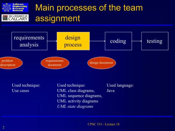
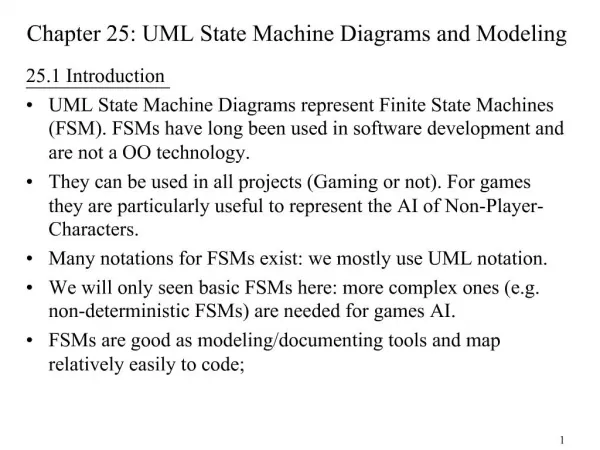
Introduction A state machine … Models the behavior of an individual object (statechart diagram) or a society of objects (activity diagram). Is a dynamic model of the system. State machines come in two varieties: Activity diagrams - usually “completion-of-activity” driven. Statechart diagrams - usually event-driven. Events trigger activities which, in turn, trigger actions. Actions are atomic. Actions may cause the return of a value or the change of state of an object. 2
Introduction A statechart diagram, also known as state diagram, models the dynamic aspects of the system by showing the flow of control from state to state for a particular class. Every class will may have its own statechart diagram. In practice, only classes with interesting or complex internal behavior will be modeled with statechart diagrams. Statechart diagrams are not shared among classes. 3
Introduction Whereas an activity diagram models the flow of control from activity to activity, a statechart diagram models the flow of control from event to event. Statechart diagrams show how an object reacts to external events or conditions during the course of its lifetime. Useful in modeling real-time systems or the part of a system that interacts with a human user. 4
Terms and Concepts State A state is a condition or situation during the life of an object in which it satisfies some condition, performs some activity, or waits for some event. A state may include … Name Entry/exit actions Internal transitions Activities Substates - may sequential or concurrent Deferred events (infrequently used) 8
Terms and Concepts State Special categories of states Initial state - indicates the initial starting state for for the state machine or a substate. Final state - indicates the state machine’s execution has completed. Real-time state machines frequently do not include a final state. Neither initial or final states contain any of the parts found in traditional states. 9
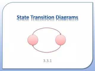
Terms and Concepts Transition A directed relationship between two states. A flow of control through a statechart diagram. Contains five parts Source state - current state before transition fires. Event trigger - external stimulus that has the potential to cause a transition to fire. Guard condition - a condition that must be satisfied before a transition can fire. Action - an executable atomic computation. Target state - new state after transition fires. 10
Terms and Concepts Advanced States and Transitions Entry action - Upon each entry to a state, a specified action is automatically executed. Syntax (to be placed inside the state symbol): entry / action Exit action - Just prior to leaving a state, a specified action is automatically executed. Syntax (to be placed inside the state symbol): exit / action 12
Terms and Concepts Advanced States and Transitions Internal Transitions - The handling of an event without leaving the current state. Used to avoid a states entry and exit actions. Syntax (to be placed inside the state symbol): event / action Activities - Ongoing work that an object performs while in a particular state. The work automatically terminates when the state is exited. Syntax (to be placed inside the state symbol): do / activity Activities are ongoing operations; actions are instantaneous operations. 13
Terms and Concepts Advanced States and Transitions Deferred Event - An event whose occurrence is responded to at a later time. Syntax (to be placed inside the state symbol): event / defer Once an event has been deferred it remains deferred until a state is entered where that particular type of event is not listed as deferred. The state diagram then responds to the event as if it had just occurred. 15
Terms and Concepts Advanced States and Transitions Simple state - A state that contains no substates. Composite state - A state that contains substates. Substate - A state that is nested inside another state. Substates allow state diagrams to show different levels of abstraction. Substates may be sequential or concurrent. Substates may be nested to any level. 16
Terms and Concepts Advanced States and Transitions Sequential Substates - The most common type of substate. Essentially, a state diagram within a single state. The “containing” state becomes an abstract state. The use of substates simplifies state diagrams by reducing the number of transition lines. A nested sequential state diagram may have at most one initial state and one final state. 17
Terms and Concepts Advanced States and Transitions History States - Allows an object to remember which substate was last active when the containing state was exited. Upon re-entry to the containing state, the substate that was last active will be re-entered directly. 20
Terms and Concepts Advanced States and Transitions Concurrent Substates - Used when two or more state diagrams are executing concurrently within a single object. Allows an object to be in multiple states simultaneously. The concurrent state diagrams within a “containing” state must begin and end execution simultaneously. If one concurrent state diagram finishes first, it must wait for the others to complete before exiting the containing state. 21