Download
1 / 21
230 likes | 556 Views
State Transition Diagrams. The state transition diagram. So far we have not discussed any method for designing sequential circuits We will only look at the design of synchronous sequential circuits in this course

E N D
The state transition diagram • So far we have not discussed any method for designing sequential circuits • We will only look at the design of synchronous sequential circuits in this course • State transition diagrams are a graphical way of representing the behaviour of a sequential system
Lighting up • Consider the status of two LED’s counting a sequence: Represents 01 1 Represents 11 If a one is added (input, say), the display moves to a new state
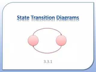
STD a, 01 1 b, 11 0 On an input of 1, this device goes from state a to state b • States can be represented by circles containing a symbol for the state, and the value of the output associated with the state • A state can return to itself • The numbers represent the inputs that moved the state machine from 1 state to another state.
a,00 b,01 d,11 c,10 Counter diagram and table 1 0 0 • e.g. state transition diagram for a 2 bit up counter • 0 inputs leave the state unchanged • The complete set of states and associated outputs can be shown in a state transition table 1 1 1 0 0
State assignment table • The next stage is to encode the states, there are 4 so it can be done in 2 bits: • Given this, we can proceed to a state assignment table, where everything is represented in terms of 1’s and 0’s:
a,00 b,01 d,11 c,10 Truth Table • By taking the inputs (present state and input) and putting them in a truth table we can develop logic expressions for the next state and outputs: 1 0 0 1 1 1 0 0 This line indicates: In state b, when the input is 1, the next state is c and the output is 01
Truth Table • The next step is to develop the logic expressions for N1, N0 O1 O0 from the truth table, either by algebra, inspection or Karnaugh map, whichever is easiest. A judicious choice of state codes makes the outputs straightforward: O1 = P1 and O0 = P0 Maps for N1 and N0 appear on the next slide
K Maps Fill in the maps and derive expressions for N1 and N0 N1 N0
K Maps N1 N0 Solution: N1 = P1.P0.I + P1.I + P1.P0 N0 = P0.I + P0.I
next state logic circuit Combinational circuit to determine outputs Present State register Next State Present State Outputs Inputs clk Welcome to the machine • A General Sequential machine consists of two main blocks • edge triggered register to hold present state • logic circuits to derive the next state and outputs using the present state and external inputs • Machine changes state on active clock edge • In some cases the next state and output logic might be combined in the same block of, eg PAL logic).
Specific Implementation • In the case of our simple binary counter: N1 = P1.P0.I + P1.I + P1.P0 N0 = P0.I + P0.I next state register for present state present state in this case actual outputs match present state clock On the clock edge, the register changes to the next stage present on the inputs, O1 = P1 and O0 = P0 logic determining outputs and next states
Worked Example • The next few slides have blanks for you to fill in as the lecture progresses. • This example takes us through the process needed to design any sequential circuit. • The example is a two bit counter that can count up or down, depending upon the input, U. • U = 1, count up, U = 0, count down
The state transition diagram Stage 1, construct the state transition diagram showing 4 possible states (a, b, c, d), the outputs at each stage and the two possible inputs (1 or 0) that moved the machine from state to state: a,00 1 b,01 0 c,10 d,11 U = 1, count up, U = 0, count down
The state table • Complete the state table
Allocate binary values to states • Probably it will simplify things if the present state code is made equal to the output code for that state.
State Assignment Table • At this stage we will take the inputs as present state (A and B), input U and outputs are the next state (C and D and the output required P and Q). These can be put in a truth table.
Derive the logic Expressions • via Karnaugh maps or otherwise determine expressions for outputs C, D, P and Q C D P Q
Logic Expression Determine the logic expressions from the K Map. • C = A.B.U + A.B.U + A.B.U + A.B.U • D = B • P = A • Q = B
A P C A next state logic circuit Q D B Q D B Q D Q Q clk Implement the machine • Combinational logic block obtained from expressions. Implemented here in programmable AND, fixed OR circuit (PAL). A B U Next state logic circuit C D P Q
Summary of General State Machines • A method has been presented for the design of general state machines The stages were: • Construct a state transition diagram for the problem • construct a state table • construct a state assignment table • Implement machine