Download
1 / 144
1.48k likes | 1.71k Views
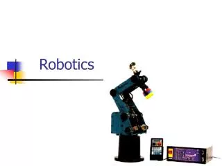
ROBOTICS. Khwaja Izhar Ahmad Associate Professor, Anjuman College of Engineering & Tech Sadar , Nagpur.440001. CO. The student will be able to define robots and their various characteristics.

E N D
ROBOTICS KhwajaIzhar Ahmad Associate Professor, Anjuman College of Engineering & Tech Sadar, Nagpur.440001
CO • The student will be able to • define robots and their various characteristics
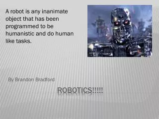
The RIA (Robotics Industries Association) has officially given the definition for Industrial Robots. “An Industrial Robot” is a reprogrammable, multifunctional manipulator designed to move materials, parts, tools, or special devices through variable programmed motions for the performance of a variety of tasks.”
Definition • Industrial robot as defined by ISO 8373: • An automatically controlled, reprogrammable, multipurpose manipulator programmable in three or more axes, which may be either fixed in place or mobile for use in industrial automation applications. • Reprogrammable: whose programmed motions or auxiliary functions may be changed without physical alterations; • Multipurpose: capable of being adapted to a different application with physical alterations; • Physical alterations: alteration of the mechanical structure or control system except for changes of programming cassettes, ROMs, etc. • Axis: direction used to specify the robot motion in a linear or rotary mode
History of industrial robotics • “Robot” Word entered English language in 19920 through a Czechoslovakian play “ Rossum’s universal Robots” by Karelcapek. Robota means forced labour in Czech. • 1954: The first programmable robot is designed by George Devol. He coins the term UniversalAutomation. • 1956:Devol and engineer Joseph Engelberger form the world's first robot company, Unimation. • 1962: The first industrial robot was online in a General Motors automobile factory in New Jersey. It was Devol and Engelberger's UNIMATE. It performed spot welding and extracted die castings. • 1973:German robotics company, KUKA, creates the first industrial robot with six electromechanically-driven axes. It is called the Famulus.
1974:Industrial robots were developed and installed in Fanuc factory. Dr. Inaba, President of FANUC was rewarded with "the 6th Annual Memorial Award of Joseph Marie Jacquard" by the American NC Society. • 1977: The Motoman L10 was introduced. It featured five axes and a maximum workload of 10 kg, which included thegripper. It weighed 470kg. • 1978:Vicarm, Unimation creates the PUMA (Programmable Universal Machine for Assembly) robot with support from General Motors. • 1979:Nachi developed the first motor-driven robots for spot welding. • 1992:FANUC Robot School was established. • 2003:OTC DAIHEN introduced the Almega AX series, a line of arc welding and handling robots.
Terms • Robot: An electromechanical device with multiple degrees-of-freedom (DOF) that is programmable to accomplish a variety of tasks. • Robotics: The science of robots. Humans working in this area are called roboticists. • DOF: Degrees-of-freedom, the number of independent motions a device can make. Also called mobility. • Manipulator :Electromechanical device capable of interacting with its environment. • Anthropomorphic : Designed or appearing like human beings. • End-effector: The tool, gripper, or other device mounted at the end of a manipulator, for accomplishing useful tasks. • Workspace: The volume in space that a robot’s end-effector can reach, both in position and orientation.
Position: The translational (straight-line) location of an object. • Orientation: The rotational (angular) location of an object. An airplane’s orientation is measured by roll, pitch, and yaw angles. • Pose: Position and orientation taken together. • link : A rigid piece of material connecting joints in a robot. • Joint: The device which allows relative motion between two links in a robot. • Kinematics:- The study of motion without regard to forces/torques. • Dynamics:- The study of motion with regard to forces/torques. • Actuators:-Provides force/torque for robot motion. • Sensor:- Reads actual variables in robot motion for use in control.
Anatomy of Robot • The Anatomy of Industrial Robots deals with the assembling of outer components of a robot such as wrist, arm, and body. Some of the key facts about robot anatomy are as below. • End Effectors: A hand of a robot is considered as end effectors. The grippers and tools are the two significant types of end effectors. The grippers are used to pick and place an object, while the tools are used to carry out operations like spray painting, spot welding, etc. on a work piece. • Robot Joints: The joints in an industrial robot are helpful to perform sliding and rotating movements of a component. • Manipulator: The manipulators in a robot are developed by the integration of links and joints. In the body and arm, it is applied for moving the tools in the work volume. It is also used in the wrist to adjust the tools. • Kinematics: It concerns with the assembling of robot links and joints. It is also used to illustrate the robot motions.
Robot Joints • In a robot, the connection of different manipulator joints is known as Robot Links, and the integration of two or more link is called as Robot Joints. A robot link will be in the form of solid material, and it can be classified into two key types – input link and output link. The movement of the input link allows the output link to move at various motions. An input link will be located nearer to the base. • The Robot Joints is the important element in a robot which helps the links to travel in different kind of movements. • There are five major types of joints such as: • Rotational joint • Linear joint • Twisting joint • Orthogonal joint • Revolving joint
Rotational Joint: Rotational joint can also be represented as R – Joint. This type will allow the joints to move in a rotary motion along the axis, which is vertical to the arm axes. • Linear Joint: Linear joint can be indicated by the letter L – Joint. This type of joints can perform both translational and sliding movements. These motions will be attained by several ways such as telescoping mechanism and piston. The two links should be in parallel axes for achieving the linear movement. • Twisting Joint: Twisting joint will be referred as V – Joint. This joint makes twisting motion among the output and input link. During this process, the output link axis will be vertical to the rotational axis. The output link rotates in relation to the input link.
Orthogonal Joint: The O – joint is a symbol that is denoted for the orthogonal joint. This joint is somewhat similar to the linear joint. The only difference is that the output and input links will be moving at the right angles. • Revolving Joint: Revolving joint is generally known as V – Joint. Here, the output link axis is perpendicular to the rotational axis, and the input link is parallel to the rotational axes. As like twisting joint, the output link spins about the input link.
Basic Robot Motions • Arm and body motions 1. Vertical traverse: Up and down motion of the arm, caused by pivoting the entire arm about a horizontal axis or moving the arm along a vertical slide. 2. Radial traverse: extension and retraction of the arm (in and out movement) 3. Rotational traverse: rotation about the vertical axis (right or left swivel of the robot arm) Wrist Motion Wrist swivel: Rotation of the wrist Wrist bend: Up or down movement of the wrist, this also involves rotation movement. Wrist yaw: Right or left swivel of the wrist.
Manipulator An industrial robot is comprised of a robot manipulator, power supply, and controllers. Robotic manipulators can be divided into two sections, each with a different function: • Arm and Body - The arm and body of a robot are used to move and position parts or tools within a work envelope. They are formed from three joints connected by large links. • Wrist- The wrist is used to orient the parts or tools at the work location. It consists of two or three compact joints. • Robot manipulators are created from a sequence of link and joint combinations. The links are the rigid members connecting the joints, or axes. The axes are the movable components of the robotic manipulator that cause relative motion between adjoining links. The mechanical joints used to construct the robotic arm manipulator consist of five principal types. Two of the joints are linear, in which the relative motion between adjacent links is non-rotational, and three are rotary types, in which the relative motion involves rotation between links.
Manipulators • Manipulator consists of joints and links • Joints provide relative motion • Links are rigid members between joints • Various joint types: linear and rotary • Each joint provides a “degree-of-freedom” • Most robots possess five or six degrees-of-freedom
Degrees of freedom Degree of Freedom is the number of independent relative motion in the form of translation and rotation The body in space has got the maximum of 6 degrees of motion(3 translatory & 3 rotary motions) Each Translatory has 1 DOF and each Rotary has 1 DOF
Common Robots Configuration • Articulated - This robot design features rotary joints and can range from simple two joint structures to 10 or more joints. The arm is connected to the base with a twisting joint. The links in the arm are connected by rotary joints. Each joint is called an axis and provides an additional degree of freedom, or range of motion. Industrial robots commonly have four or six axes.
Cartesian - These are also called rectilinear or gantry robots. Cartesian robots have three linear joints that use the Cartesian coordinate system (X, Y, and Z). They also may have an attached wrist to allow for rotational movement. The three prismatic joints deliver a linear motion along the axis. • The first type of robot is called Cartesian Robot. This type of robot uses X,Y,Z three dimensional system to control movement and location
Cartesian/Rectangular Manipulator • straight, or linear motion along three axes: • in and out, (x) • back and forth (y) • up and down (z)
Cylindrical - The robot has at least one rotary joint at the base and at least one prismatic joint to connect the links. The rotary joint uses a rotational motion along the joint axis, while the prismatic joint moves in a linear motion. (P joint, R joint, P joint). Cylindrical robots operate within a cylindrical-shaped work envelope.
Cylindrical Manipulator Rotation about the base or shoulder. (θ) up and down (z) in and out (R)
Polar - Also called spherical robots, in this configuration the arm is connected to the base with a twisting joint and a combination of two rotary joints and one linear joint. The axes form a polar coordinate system and create a spherical-shaped work envelope.
Polar or Spherical Manipulator • rotation about the base • Rotation about an axis in the vertical plane to raise and lower it. • reaches in and out.
SCARA - Commonly used in assembly applications, this selectively compliant arm for robotic assembly is primarily cylindrical in design. It features two parallel joints that provide compliance in one selected plane.
SCARA Robot • Selective Compliance Assembly Robot Arm • the same work area as a cylindrical-coordinates robot. • the reach axis includes a rotational joint in a plane parallel to the floor.
Delta - These spider-like robots are built from jointed parallelograms connected to a common base. The parallelograms move a single EOAT in a dome-shaped work area. Heavily used in the food, pharmaceutical, and electronic industries, this robot configuration is capable of delicate, precise movement
Basic Robot motions A robot manipulator can make four types of motion in travelling from one point to another in the workplace: • Slew motion : simplest type of motion. Robot is commanded to travel from one point to another at default speed. • Joint-interpolated motion: requires the robot controller to calculate the time it will take each joint to reach its destination at the commanded speed. • Straight-line interpolation motion: requires the end of the end effector to travel along a straight path determine in rectangular coordinates. • Useful in applications such as arc welding, inserting pins into holes, or laying material along a straight path. • Circular interpolation motion: requires the robot controller to define the points of a circle in the workplace based on a minimum of three specified positions. • Circular interpolation produces a linear approximation of the circle and is more readily available using a programming language rather than manual or teach pendant techniques.
Motion system • 1. Point-to-point (PTP) control robot: is capable of moving from one point to another point. The locations are recorded in the control memory. PTP robots do not control the path to get from one point to the next point. Common applications include component insertion, spot welding, hole drilling, machine loading and unloading, and crude assembly operations.
Point to point control Point-To-Point: These robots are most common and can move from one specified point to another but cannot stop at arbitrary points not previously designated. • All Axes start and end simultaneously • All Geometry is computed for targets and relevant Joint changes which are then forced to be followed during program execution • Only the end points are programmed, the path used to connect the end points are computed by the controller • user can control velocity, and may permit linear or piece wise linear motion • Feedback control is used during motion to ascertain that individual joints have achieved desired location • Often used hydraulic drives, recent trend towards servomotors • loads up to 500lb and large reach Applications • pick and place type operations • palletizing • machine loading
2. Continuous-path (CP) control robot: with CP control, the robot can stop at any specified point along the controlled path. All the points along the path must be stored explicitly in the robot’s control memory. Typical applications include spray painting, finishing, gluing, and arc welding operations.
Continuous path control Continuous Path: • It is an extension of the point-to-point method. this involves the utilization of more points and its path can be arc, a circle, or a straight line. • Because of the large number of points, the robot is capable of producing smooth movements that give the appearance of continuous or contour movement. • In addition to the control over the endpoints, the path taken by the end effector can be controlled • Path is controlled by manipulating the joints throughout the entire motion, via closed loop control. Applications • spray painting • polishing • grinding • arc welding
3. Controlled-path robot: the control equipment can generate paths of different geometry such as straight lines, circles, and interpolated curves with a high degree of accuracy. All controlled-path robots have a servo capability to correct their path.
Controlled Path Controlled Path: It is a specialized control method that is a part of general category of a point-to-point robot but with more precise control. The controlled path robot ensures that the robot will describe the right segment between two taught points. Controlled-path is a calculated method and is desired when the manipulator must move in the perfect path motion.
Basic control system concepts - control system analysis - robot actuation and fed back, Manipulators – direct and inverse kinematics, Coordinate transformation - Brief Robot dynamics. Types of Robot and effectors -Grippers - Tools as end effectors - Robot/End - effort interface.
Basic control system concepts Open-Loop Control Systems Closed-Loop Control Systems Multivariable Control Systems
Actuating Device Desired Out put Response Process Output • Closed-Loop Control Systems utilizes feedback to compare the actual output to the desired output response Desired Out put Response Process Controller Output Comparison Measurement Open-Loop Control Systems utilize a controller or control actuator to obtain the desired response.
Multivariable Control Systems Desired output Response Output Variables Controller Process Measurement
Technical Robotics Terms • Speed: Speed is the amount of distance per unit time at which the robot can move, usually specified in inches per second or meters per second. The speed is usually specified at a specific load or assuming that the robot is carrying a fixed weight. Actual speed may vary depending upon the weight carried by the robot. • Load Bearing Capacity(Payload) : Load bearing capacity is the maximum weight-carrying capacity of the robot. Serial robots that carry large weights, but must still be precise, are heavy and expensive, with poor (low) payload-to weight ratios. • Control Resolution: This is the smallest change that can be measured by the feedback sensors, or caused by the actuators, whichever is larger. If a rotary joint has an encoder that measures every 0.01 degree of rotation, and a direct drive servo motor is used to drive the joint, with a resolution of 0.5 degrees, then the control resolution is about 0.5 degrees (the worst case can be 0.5+0.01).