Download
1 / 34
350 likes | 471 Views
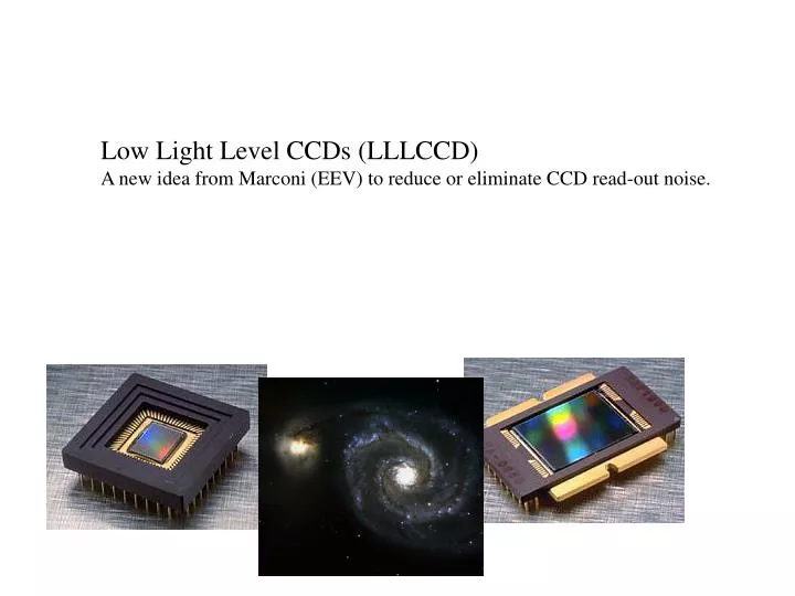
Low Light Level CCDs (LLLCCD) A new idea from Marconi (EEV) to reduce or eliminate CCD read-out noise. CCD Analogy. VERTICAL CONVEYOR BELTS ( CCD COLUMNS ). RAIN ( PHOTONS ). BUCKETS ( PIXELS ). MEASURING CYLINDER ( OUTPUT AMPLIFIER ). HORIZONTAL CONVEYOR BELT ( SERIAL REGISTER ).

E N D
Low Light Level CCDs (LLLCCD) A new idea from Marconi (EEV) to reduce or eliminate CCD read-out noise.
CCD Analogy VERTICAL CONVEYOR BELTS (CCD COLUMNS) RAIN (PHOTONS) BUCKETS (PIXELS) MEASURING CYLINDER (OUTPUT AMPLIFIER) HORIZONTAL CONVEYOR BELT (SERIAL REGISTER)
Photomicrograph of a corner of an EEV CCD. Image Area Serial Register Bus wires Edge of Silicon Read Out Amplifier
p-type silicon n-type silicon Charge Collection in a CCD. Photons entering the CCD create electron-hole pairs. The electrons are then attracted towards the most positive potential in the device where they create ‘charge packets’. Each packet corresponds to one pixel. pixel boundary pixel boundary incoming photons Electrode Structure Charge packet SiO2 Insulating layer
Conventional Clocking 1 Insulating layer Surface electrodes Charge packet (photo-electrons) N-type silicon P-type silicon Potential Energy Charge packets occupy potential minimums
Conventional Clocking 2 Potential Energy
Conventional Clocking 3 Potential Energy
Conventional Clocking 4 Potential Energy
Conventional Clocking 5 Potential Energy
Conventional Clocking 6 Potential Energy
Conventional Clocking 7 Potential Energy
Conventional Clocking 8 Potential Energy
Conventional Clocking 9 Potential Energy
Conventional Clocking 10 Charge packets have moved one pixel to the right Potential Energy
LLLCCD Gain Register Architecture Conventional CCD LLLCCD Image Area (Architecture unchanged) Image Area On-Chip Amplifier On-Chip Amplifier { Serial register Serial register Gain register The Gain Register can be added to any existing design
Multiplication Clocking 1 In this diagram we see a small section of the gain register Gain electrode Potential Energy
Multiplication Clocking 2 Gain electrode energised. Charge packets accelerated strongly into deep potential well. Energetic electrons loose energy through creation of more charge carriers (analogous to multiplication effects in the dynodes of a photo-multiplier) . Gain electrode Potential Energy Potential Energy
Multiplication Clocking 3 Clocking continues but each time the charge packets pass through the gain electrode, further amplification is produced. Gain per stage is low, <1.015, however the number of stages is high so the total gain can easily exceed 10,000 Potential Energy Potential Energy
Multiplication Clocking 4 The Multiplication Register has a gain strongly dependant on the clock voltage
Conventional CCD SNR Equation SNR = Q.I.t.[Q.t.( I +BSKY) +Nr2 ]-0.5 Q = Quantum Efficiency I = Photons per pixel per second t = Integration time in seconds BSKY = Sky background in photons per pixel per second Nr = Amplifier (read-out) noise in electrons RMS Noise Equations 1. Very hard to get Nr < 3e, and then only by slowing down the readout significantly. At TV frame rates, noise > 50e Trade-off between readout speed and readout noise
LLLCCD SNR Equation SNR = Q.I.t.Fn.[Q.t.Fn.( I +BSKY) +(Nr/G)2 ]-0.5 G = Gain of the Gain Register Fn = Multiplication Noise factor = 0.5 Noise Equations 2. With G set sufficiently high, this term goes to zero, even at TV frame rates. Unfortunately, the problem of multiplication noise is introduced Readout speed and readout noise are decoupled
Ideal Histogram, StdDev=Gain x (Mean Illumination in electrons )0.5 Actual Histogram, StdDev=Gain x (Mean Illumination in electrons )0.5 x M Probability Electrons per pixel at output of multiplication register Multiplication Noise 1. In this example, A flat field image is read out through the multiplication register. Mean illumination is 16e/pixel. Multiplication register gain =100 Histogram broadened by multiplication noise M=1.4
Multiplication Noise 2. Multiplication noise has the same effect as a reduction of QE by a factor of two. In high signal environments , LLLCCDs will generally perform worse than conventional CCDs. They come into their own, however, in low signal, high-speed regimes.
Photon Counting 1. Offers a way of removing multiplication noise. Photo-electron detection threshold CCD Video waveform No photo-electron One photo-electron One photo-electron No photo-electron Two photo-electrons No photo-electron Co-incidence loss here Photo-electron detection pulses Fast comparator CCD Approx 100ns SNR = Q.I.t.[Q.t.( I +BSKY)]-0.5 Noiseless Detector
Photon Counting 2. If exposure levels are too high, multi-electron events will be counted as single-electron events, leading to co-incidence losses . This limits the linearity and reduces the effective QE of the system. In the case of a hypothetical 1K x 1K photon counting CCD, the maximum frame rate would be approximately 10Hz. If we can only accept 5% non-linearity then the maximum illumination would be approximately 1 photo-electron per pixel per second.
Summary. The three operational regimes of LLLCCDs 1) Unity Gain Mode. The CCD operates normally with the SNR dictated by the photon shot noise added in quadrature with the amplifier read noise. In general a slow readout is required (300KPix/second) to obtain low read noise (4 electrons would be typical). Higher readout speeds possible but there will be a trade-off with the read-noise. 2) High Gain Mode. Gain set sufficiently high to make noise in the readout amplifier of the CCD negligible. The drawback is the introduction of Multiplication Noise that reduces the SNR by a factor of 1.4. Read noise is de-coupled from read-out speed. Very high speed readout possible, up to 11MPixels per second, although in practice the frame rate will probably be limited by factors external to the CCD. 3) Photon Counting Mode. Gain is again set high but the video waveform is passed through a comparator. Each trigger of the comparator is then treated as a single photo-electron of equal weight. Multiplication noise is thus eliminated. Risk of coincidence losses at higher illumination levels.
Possible Application 1. Acquisition Cameras Performance at CASS of WHT analysed below. The calculated SNR is for a single TV frame (40ms). It is assumed that the seeing disc of the target star evenly illuminates 28 pixels (0.6” seeing, 0.1”/pixel plate scale). SNR calculated for each pixel of the image. Assumptions: CCD QE=85%, LLLCCD QE=30%, Image Tube QE =11% dark of moon, seeing 0.6”, 24um pixels (0.1”per pixel), 25Hz frame rate
Possible Application 2. Acquisition Cameras As for the previous slide but instead the exposure time is increased to 10s
Possible Application 3. Photon Counting Faint Object Spectroscopy LLLCCDs operating in photon counting mode would seem to offer some promise. The graph below shows the time taken to reach a SNR=3 for various source intensities QE=70% Amplifier Noise =5e Background =0.001 photons per pixel per second
Possible Application 4. Wave Front Sensors Algorithm used on the current NAOMI WFS produces reliable centroid data when total signal per sub-aperture exceeds about 60 photons. Amplifier Noise=5e QE= 70%
Marconi LLLCCD Products 1. CCD65 Aimed at TV applications as a substitute for image tube sensors. 576 x 288 pixels. Thick frontside illuminated, peak QE of 35%. 20 x 30um pixels CCD 60 128x 128 pixel, thinned, has been built but still under development. For possible application to Wavefront Sensing. CCD 79,86,87 Proposed future devices up to 1K square, > 10 frames per second readout at sub-electron noise levels. Camera systems based on this chip available winter 2001 Would subtend 51” x 39” at WHT CASS Low Priority for Marconi without encouragement from the astronomical community As above
Marconi LLLCCD Products 2. L3CS Packaged camera containing TE cooled CCD65 frontside illuminated 20ms-100sec integration times 2e per pix per sec dark current Binning and Windowing available Firewire Interface +video output Available towards end of 2001 (£25K) L3CA Packaged camera containing TE cooled CCD65 frontside illuminated 20ms-100sec integration times <1e per pix per sec dark current Binning available video output