Download
1 / 26
260 likes | 325 Views
The innovative adaptive electric drive incorporates an adaptive gear variator, offering simplicity, self-regulation, adaptability, and reliability. Developed based on Professor Ivanova K.S.'s discovery, this drive is recognized in international publications and patents.

E N D
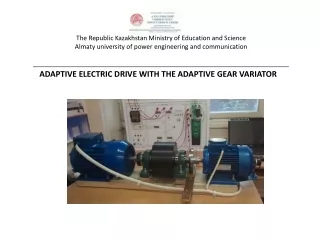
The Republic Kazakhstan Ministry of Education and ScienceAlmaty university of power engineering and communication________________________________________________________________________ ADAPTIVE ELECTRIC DRIVE WITH THE ADAPTIVE GEAR VARIATOR
ABSTRACT • The adaptive electric drive contains the electric motor and an adaptive gear variator. The adaptive gear variator represents a wheelwork with constant cogging of toothed wheels and with the variable transfer relation created by external loading. The variator works without a control system. The variator is created on the basis of a discovery of professor Ivanova K.S. «Effect of power adaptation in the mechanic». The essence of opening - a planetary kinematic chain with two degree of freedom in which toothed wheels form the mobile closed contour, adapts for a variable load by independent speed control of motion of toothed wheels in a contour under the influence of loading. • The basic advantages of an adaptive gear variator in comparison with existing mechanisms with the variable transfer relation: • 1. Unprecedented simplicity of a design and service. • 2. Self-regulation (work without a control system). • 3. Full and instant adaptation to a variable load. • 4. Small sizes and weight. • 5. High reliability and durability. • 6. Low cost. • Novelty of the adaptive electric drive • It is defined by numerous international publications in rating publications and patents of Kazakhstan, Russia and Germany
PATENT OF GERMANY
PATENT OF RUSSIA
PATENT OF KAZAKHSTAN
PATENT OF KAZAKHSTAN
6 3 5 2 7 B K 9 10 11 1 8 A 4 4 1. DESCRIPTION OF ADAPTIVE GEAR VARIATOR The adaptive gear variator (fig. 1) contains following details: the entrance carrier 9, the entrance satellite 2, the block of the solar wheels 1-4 fixed on intermediate shaft, the block of ring wheels 3-6, the target satellite 5 and the target carrier 10. Toothed wheels 1, 2, 3, 6, 5, 4 form the mobile closed contour with dynamic constraint. Toothed wheels 8, 7 form additional parallel transfer from the carrier 9 on the satellite 5. Fig. 1. The circuit design of an adaptive gear variator
SPACE IMAGE OF DETAILS OF THE VARIATOR • The variator contains following details: • 1 - the entrance carrier, 2-3 - the entrance satellite, 4 - a solar wheel of the block of solar wheels, 5-6 - the block of ring wheels, 7-8 - the target satellite in the block with a wheel 12 additional transfers, 9 - a solar wheel of the block of solar wheels on intermediate to the shaft 15, 10 - the target carrier, 11 - a toothed wheel of additional transfer together with a fastening disk to the entrance carrier 1. Fig. 2. Space image of details of a variator
2. DESIGN OF THE ADAPTIVE GEAR VARIATOR Knots of a gear variator: 1. The entrance half-coupling. 2. An entrance cover with the entrance bearing of the case. 3. The mobile case with gear rings and a target cover. 4. The entrance carrier as an assembly. 5. The target carrier as an assembly. 6. The target bearing of the case. 7. The target half-coupling Fig. 3. A design of knots of the gear adaptive variator
3. WORK OF THE ADAPTIVE GEAR VARIATOR. • The variator works as follows (fig. 1). • The input shaft with the input carrier 9 transfers motion to the input satellite 2. The input satellite 2 transfers motion to block of gears 1 -4 and 3-6. Blocks of wheels 1-4 and 3-6 transfer motion to the output satellite 5 and the output carrier 10. Simultaneously the kinematic chain with additional parallel transfer in the form of toothed wheels 8-7 transfers motion from the entrance carrier 9 to the output satellite 5 and to the carrier 10. Parallel transfer 8-7 has the transfer ratio equal to the transfer ratio of a planetary kinematic chain. • Definability of motion at the moment of start is provided with additional constraint which creates a dead position of carriers of equal length. At once after the motion beginning there is an unblocking of a dead position and transition in a condition to two degree of freedom. The unblocking is created by the additional parallel transfer 8-7 doubling the chocked planet gear. • In an operational regime of motion with two degree of freedom the toothed wheels forming the closed contour 1-2-3-6-5-4 provide energy circulation. The closed contour creates the differential (mobile) constraint analogous to constraint which creates a circulating fluid stream in the hydraulic converter. Thus the range of transfer relations of the gear variator depending only from numbers of teeth of wheels has no the restrictions peculiar to the hydraulic transformer.
4. DEMONSTRATION OF ANIMATION MODEL OF THE GEAR VARIATOR Открыть файл: Щелкнуть правой кнопкой – Нажать «Объект упаковщика для оболочки»–«Активизация содержимого» -«Запустить» On animation model of a variator the propeller (grey colour on the right) sets in a variator containing the entrance carrier with the entrance satellite of green colour, the block of solar wheels of red colour, the block of ring wheels of violet colour and the target carrier with the green target satellite. Loading is created by a brake of red colour at the left. Arrow keys allow to change a rule of animation model Work explanation: The propeller twirls the entrance carrier with constant angular speed. In the beginning works the brake (red colour at the left) creates the brake moment, equal to the propeller moment. The closed contour containing satellites and toothed wheels is twirled as a single whole without internal relative mobility. The delivery speed of twirl of the target carrier is equal to speed of twirl of the entrance carrier. After increase in a target moment of resistance by pressure of key W with some deduction the brake retards twirl of the target carrier. The target carrier starts to lose the entrance carrier. Internal motion of wheels in the closed contour, characterising dynamic communication begins. Energy circulation in the closed contour leads to change of parametres of the power transferred to the output shaft - the moment of resistance increases, and speed of twirl decreases. Repeated pressure of key W with deduction creates additional increase in a moment of resistance and additional delay of motion of the output shaft. The more external loading, the more intensively energy circulation in the closed contour. If to reduce loading (pressure and deduction of key Q) the delivery speed of the target carrier with the target satellite will start to increase. The target carrier will catch up with the entrance carrier on speed of twirl. After achievement of the minimum moment of resistance angular speeds of the entrance and target drove will be made even, the closed contour will move as a single whole. Energy circulation will stop. Power interacting entrance and the variator output shaft results according to law of conservation of energy in balance of a tractive power and power of resistance . После достижения минимального момента сопротивления угловые скорости входного и выходного водил сравняются, замкнутый контур будет двигаться как одно целое. Циркуляция энергии прекратится. Силовое взаимодействие входного и выходного вала вариатора приводит в соответствии с законом сохранения энергии к балансу тяговой мощности и мощности сопротивления . Отсюда следует (1). – эффект силовой адаптации. Здесь - входной движущий момент и выходной момент сопротивления, - входная и выходная угловые скорости вариатора.
4. THE TEST-BED FOR TESTING OF THE GEAR VARIATOR The test-bed (fig. 4) is intended for performance of experimental researches of a variator for the purpose of an estimation of reliability of its working capacity and conformity of its act to the found theoretical regularity. 4 1 2 3 5 Fig. 4. Test – bed for testing On the test-bed following devices are shown: the basic propeller 1, an adaptive gear variator 2, the auxiliary (brake) propeller 3, the instrument panel 4, the monitor 5. Working process of a variator on the test-bed is displaid under indications of devices on the panel of the stand and on the monitor shield. Conducting of tests of a variator was carried out in a regime of smooth decrease of a brake moment of resistance from a starting maximum to null. The primary goal of conducting of experiment in motion operating conditions was determination of the fact of self-regulation of speed of twirl at loading change. The effect of power adaptation was mustered by creation of the variable brake moment of resistance opposite to a direction of twirl of the shaft of the traction engine by power кWt at the constant driving moment of traction engine nm and a constant corrected speed of the shaft of traction engine of rpm. Change of the brake moment was carried out by the frequency converter operating motion of the engine brake by means of a potentiometer. Angular speed of the output shaft of a variator with a negative sign was fixed by the revolution counter of the engine brake and reflected in the stand panel. Values of a strength of current and voltage of the traction engine and the engine brake were reflected in the stand panel also, allowing to define power of propellers
CONTINUATION Change of the brake moment was carried out by the frequency converter operating motion of the engine brake by means of a potentiometer. Angular speed of the output shaft of a variator with a negative sign was fixed by the revolution counter of the engine brake and reflected in the stand panel. Values of a strength of current and voltage of the traction engine and the engine brake were reflected in the stand panel also, allowing to define power of propellers. . Для просмотра испытаний вариатора на стенде откройте файл:
CONTINUATION Parameters of motion of the output shaft of a variator are characterised by points A, B, C, D, E, F which define a variator tractive characteristic. Parameters of motion of the output shaft of a variator are presented in table 1. Table 1 Photos of tests are resulted on fig. 5, 6, 7.
5. TRACTIVE CHARACTERISTIC OF THE ADAPTIVE GEAR VARIATOR Results of testing of a variator are reflected in the builted tractive characteristic of a variator in the form of dependence of a moment of resistance on the day off to the shaft of a variator from an output shaft rotational speed (fig. 8). The analysis of the gained data confirms presence of effect of power adaptation or self-regulation. Variable power loading calls change of target angular speed of the shaft of a variator according to the formula (2). Fig. 8. An experimental tractive characteristic of a gear variator
6. EFFICIENCY OF THE ELECTRIC DRIVE WITH THE ADAPTIVE GEAR VARIATOR The adaptive electric drive has high efficiency as the variator wheelwork works at constant contact of toothed wheels lost-free energy on switchings of steps of transfers. The electric motor for the usual drive of the car with variable technological resistance is necessary for choosing on the maximum loading. Therefore in all operating modes with the reduced loading the electric drive will have the downgraded electric efficiency (cosine fi). Especially big power losses occur because of inertia loadings at frequent start-up and stops of tools (for example, in robots and manipulators). In the electric drive with an adaptive gear variator the electric motor can be chosen not on as much as possible necessary power, and on average outlayed power (or even on the minimum power). Then at the maximum loading the tool will simply retard motion. In the electric drive with an adaptive gear variator the electric motor can be always loaded on a total output. At average loading the electric drive with an adaptive gear variator has electric efficiency (efficiency) at least on 25 % above in comparison with the usual electric drive.
7. APPLICATION OF THE ADAPTIVE ELECTRIC DRIVE WITH AN ADAPTIVE GEAR VARIATOR The adaptive gear variator can be used in all drives of cars with variable technological resistance. The most effective scopes of a variator: 1. Motor industry. (There are patents). 2. A robotics. The main advantages of a variator - small gabarits and weight at the expense of decrease of power of drives, raise of electric efficiency. (There are publications). 3. Wind-power engineering. The main advantage - reliability, trouble-free operation at squally gusts of a wind. (There are patents, publications and an exhibit of the World's fair of the EXPO 2017). 4. Pumps. Advantages - prevention of water hammers, economy of the electric power. 5. Drilling of rocks of variable hardness. (There is a patent and publications). 6. Drives rolling and drawing benches. Advantages - the automatic coordination of work of the several drives moving one installation. (There is a publication). 7. Drives of space technics. Economy of weight. (There are publications). 8. Motors-wheels of heavy transport cars. Advantages - small gabarits, self-regulation, the coordination of movements of wheels. (There is a patent and publications). 9. Electric motor cars. (There are publications). 10. Crushers and ball mills. Advantages - prevention of blows, economy of the electric power. 11. Sports transport. Efficiency raise. (There is a publication). 12. Locomotives. Efficiency raise.
CONCLUSION 1.The design of a variator with two degree of freedom and with additional dynamic communication provides an energy transfer from the traction engine on the output shaft of a variator both at start-up, and in operating conditions. 2. The variator admits an output shaft dead stop at the working traction engine. 3. The variator provides power adaptation to a variable load in work operating conditions. 4. In motion operating conditions smooth change of speed of the output shaft occurs at smooth change of a moment of resistance, both at increase, and at decrease of a moment of resistance. .
0 THANK YOU FOR ATTENTION