3 Phase Wave Generation
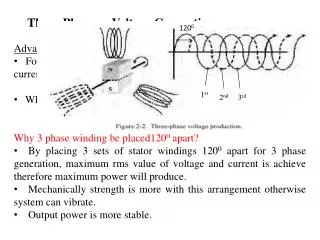
3 Phase Wave Generation. 3 Phase waveform generation using Timer/Counter1 and 3 on atmega128. Topics. Sinusoidal Wave Generation Theory Atmega128 setup and considerations Results. 3 Phase line to line voltages. uC used to control switch states +E or 0 is shown to the load on each phase


3 Phase Wave Generation
E N D
Presentation Transcript
3 Phase Wave Generation 3 Phase waveform generation using Timer/Counter1 and 3 on atmega128
Topics • Sinusoidal Wave Generation Theory • Atmega128 setup and considerations • Results
3 Phase line to line voltages • uC used to control switch states • +E or 0 is shown to the load on each phase • Depends on if upper or lower switch is on
3 Phase line to line voltages • 2/3 on switching scheme used • Allowing switches to be off for 1/3 of the time reduces switching power losses • Line to neutral voltages are not sinusoidal, but line to line are!!! *U, V, W are the desired line to neutral voltages
Topics • Sinusoidal Wave Generation Theory • Atmega128 setup and considerations • Results
uC Sinusoidal PWM • Line to neutral voltages approximated using PWM switching • Average output voltage controlled by duty cycle • uC duty cycle = OCRnA:C/Top • Top and pre-scaler are set so switching frequency is at 20kHz
Lookup Table Generation • Using Excel duty cycle of was approximated • One cycle broken up into 192 steps • Sin(2*PI*i/192), i = 0..191 • OCRnA:C = Round(Sin(2*PI*i/192)*TOP) • TOP value is 400 for my 20kHz switching frequency • Looking up values frees up uC for other tasks
i i 0-63 64-127 128-191 sine Look-Up Table Round(U*TOP) sin(2*PI*i/192)
Sin lookup table array const uint16_t sin_lookup[192*3] = { //OCRnA, OCRnB, OCRnC 0, 0, 346, 13, 0, 353, 26, 0, 359, 39, 0, 364, 52, 0, 370, 65, 0, 374, 78, 0, 379, … … }
Timer/Counter 1/3 Setup • Phase & Frequency correct PWM • Dual Slope Operation • Used to control switches • Timer/Counter1 Upper Switches • Timer/Counter3 Lower Switches • Timer/Counter 3 switches inverse of Timer/Counter 1 • Output bit is set or cleared on compare match
Timer/Counter 2 • Updates Timer/Counter1/3 OCRnA,OCRnB,OCRnC to control duty cycle • Counter variable incremented by 3 every time Timer/Counter 2 interrupts • OCRnA:C value generated from lookup table • OCRnA = sin_lookup[counter] • OCRnB = sin_lookup[counter+1] • OCRnC = sin_lookup[counter+2] • Interrupts occur fdesired*192 times per second
My epiphany + ≈ + • One output port of uC looks like one switching stage • Switches between 0 and Vcc • Upper and Lower switches never on at same time (no shoot-thru) • Using OCR1A:C of one Timer/Counter1 and the counters three output pins a three phase waveform can be generated • **Bonus** I don’t have to buy anything to implement the design
Viewing Wave forms RC filters and Resistive loads were used to view the waveforms PortB.5 PortB.6 PortB.7
Topics • Sinusoidal Wave Generation Theory • Atmega128 setup and considerations • Results
Results Waveform growth
Results A B C A-B
Shoot Thru If S+ and S- on at same time the circuit would short
Shoot Thru To avoid shoot-thru add a switching delay Amount to increment or decrement by depends on switching frequency OCR1A = OCRA-1 (cleared sooner) OCR3A = OCRA+1 (set later)
Other Considerations Make sure TCCR1 and TCCR3 are synchronous Using SFIOR Stop pre-scalers (stop the clocks) Set TCCR1 and TCCR3 to zero Restart prescalers Setting TSM, asserts a reset signal to PSR0 and PSR321. Upon clearing TSM PSR0 and PSR321 are set to zero and timers/counters begin counting synchronously
References Generate advanced PWM signals using 8-bit mCs Michael Copeland, Infineon http://www.edn.com/article/CA52686.html AP16097: Different PWM Waveforms Generation for 3-Phase AC Induction Motor with XC164CS Infineon http://www.infineon.com/cms/en/product/channel.html?channel=ff80808112ab681d0112ab6b2dfc0756 AVR447: Sinusoidal driving of three-phase permanent magnet motor using ATmega48/88/168 AVR494: AC Induction Motor Control Using the constant V/f Principle and a Natural PWM Algorithm AVR http://www.atmel.com/products/AVR/mc/?family_id=607