Download
1 / 38
380 likes | 407 Views
Learn about Glades Electric Cooperative's system restoration program ensuring maintenance of distribution, transmission systems, and substations. Includes schedules for line breakers, regulators, vegetation management, and substation maintenance.

E N D
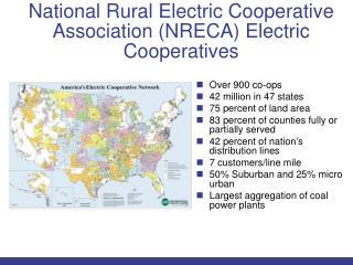
Glades Electric CooperativeInfrastructure • Miles of Line 2,213 • Overhead Dist. 2,180 • Underground Dist. 33 • Transmission 87 • 16,402 meters • Average 7 meters per mile of line
Glades Electric CooperativeMeters Served by County • Highlands 7,610 • Okeechobee 2,190 • Glades 3,197 • Hendry 3,405 Total Meters 16,402
Power Supply System Restoration The System Restoration Program (SRP) at GEC is utilized to maintain our Distribution and Transmission Systems as well as Substations. This program includes all elements of system maintenance. The program specifically addresses poles and structures, conductors, grounding, guying and inspection. Additionally the SRP includes testing, maintenance and inspection of substations.
Power Supply System Restoration Schedule The SRP was established to ensure that each and every mainline section undergoes system restoration within approximately an 8 year period. Work is divided such that approximately 1/8 of the circuits are worked each year. • Phase 1 restoration (Mainline) focuses on 3 Ø line sections that are connected directly to the supplying substation. Sections of those circuits that are downstream of three Ø or single Ø line breakers, are considered part of the mainline. • Phase 2 focuses on sections of the circuit that are fused, regardless of the number of phases, are generally considered to be taps. Any exceptions regarding the sections of circuits included in each phase will be handled on an individual basis.
Power Supply System Restoration • Poles/structures • Guys & Attachments • Cross Arms • Insulators • Switches/Fused Switches • Surge Arrestors • Transformers • Capacitors • Right of Way • Line Breakers (OCR’s) • Line Regulators • Substations • Code Violations
Power Supply System Restoration Schedule Line Breakers (OCR’s): Line breakers are addressed in the Oil Circuit Breaker Change-Out Program. Under this program, each OCR is replaced with a new/rebuilt Oil Circuit Breaker every five (5) years.
Power Supply System Restoration Schedule Line Regulators Line regulators are addressed in the Regulator Maintenance Program. Under this program, each regulator is maintained and tested every four (4) years. Additionally, each line regulator is inspected and operationally checked every quarter.
Power Supply System Restoration Schedule Right of Way Trimming Vegetation management on the GEC system is completed, by circuit, at a fixed cost to GEC. All GEC circuits are trimmed within a three year cycle.
Power Supply System Restoration Schedule Transmission System Program Each transmission line is aerially inspected on an annual basis. Items that are identified during this inspection are classified into two categories. • Category 1 consists of those items that must be addressed prior to the next inspection. • Category 2 items are less critical and are recorded on the inspection form for future reference. Items in this category are given special attention during subsequent inspections and are corrected as required.
Power Supply System Restoration Schedule Substation Program Substations are inspected two (2) times per month. One inspection is a visual inspection of the overall facility; the other inspection includes operational checks of equipment. Substation batteries are tested quarterly. Problems encountered or observed in any of these inspections are budgeted, scheduled and corrected. Problems that are deemed critical are corrected immediately.
Power Supply System Restoration Schedule Substation Major Maintenance & Testing This program is performed on each station every four (4) years and includes the following: • Circuit Switcher: Power Factor (Doble) test Clean & re-torque connections Operational Check Voltage drop-open/close Visual Inspection
Power Supply Substation Major Maintenance & Testing • Transformer: Power Factor (Doble) test Clean & re-torque connections Turns Ratio Test (TTR) Dielectric Test Oil Dissolved Gas Analysis (DGA)* *Performed annually Current Transformer (CT) test Visual Inspection
Power Supply Substation Major Maintenance & Testing • Surge Arrestors: Power Factor (Doble) test Clean & re-torque connections Visual Inspection • Bus & Bus Insulators: Visual Inspection
Power Supply Substation Major Maintenance & Testing • Circuit Breakers: Power Factor (Doble) test Clean & re-torque connections Current Transformer (CT) test Timing test Contact Resistance test (Ductor) Dielectric Oil test Hi-pot test Operational check Visual Inspection
Power Supply Substation Major Maintenance & Testing • Regulators: Power Factor (Doble) test Clean & re-torque connections Dielectric Oil test Operational check Visual Inspection • Relays: Check settings Test Clean
Transmission Upgrades • Relocated and Upgraded 4.4 miles of 69kV transmission line and distribution • Improved access • Improved sectionalizing • Upgraded line capacity • Upgraded storm strengthening • Relocated existing distribution circuit as underbuild on transmission structures • Total cost of project $1.7 million
Old Hicpochee – Hensley 69kv line in cane field Required specialized equipment during rainy season Difficult to patrol from roadway Serves 2 substations with approximately 2,178 meters
New Hensley – Hicpochee 69kV Line Improved access Improved patrolling capability Current wind loading and construction standards Relocated distribution circuit from east side of road to transmission right of way
Distribution Upgrades • Major maintenance on 23.5 miles on three distribution circuits • Complete circuit rebuild approximately 6.8 miles • Rebuilt regulator banks for higher wind resistance • Trimmed 721 miles of distribution ROW
Old Morgan Henderson Circuit 1 Area prone to flooding Specialized equipment required during rainy season
New Morgan Henderson Circuit 1 Increased distance from roadway Shorter span lengths Increased pole classification
New Morgan Henderson Circuit 1 Improved accessibility Shorter span lengths Increased pole classification
Typical Regulator Installation Wind loading often exceeded pole capacity during hurricanes Regulators prone to being blown off platform during hurricanes
New Regulator Installations Reduced wind loading Reduced equipment loss potential
Work in Progress • 2009 Strategic Work Plan • New Substation in Okeechobee • New Double Circuit Distribution Line in Okeechobee
Work in Progress • 2009 Strategic Work Plan • New Substation in Okeechobee • New Double Circuit Distribution Line in Okeechobee
Morris – Basinger 69kV Line Approximately 8 structures in retention pond Requires specialized equipment Extended outage time if repairs are required in retention pond 2,190 meters served