Download
1 / 81
910 likes | 1.39k Views
The 8051 Microcontroller. Chapter 7 ASSEMBLY LANGUAGE PROGRAMMING. Assembly language is a computer language lying between the extremes of machine language and high-level language.

E N D
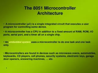
The 8051 Microcontroller Chapter 7 ASSEMBLY LANGUAGE PROGRAMMING
Assembly language is a computer language lying between the extremes of machine language and high-level language. • Assembly language replaces the binary codes of machine language with easy to remember "mnemonics" that facilitate programming. • Instructions operate on data, and the location of the data is specified by various "addressing modes" embedded in the binary code of the machine language instruction.
An assembly language program is a program written using labels, mnemonics, and so on, in which each statement corresponds to a machine instruction. Often called source code or symbolic code. • A machine language program is a program containing binary codes that represent instructions to a computer. Often called object code. Executable by a computer. • An assembler is a program that translates an assembly language program into a machine language program. Object code may be in "absolute" or in "relocatable" form. In the latter case, "linking" is required to set the absolute address for execution. • A linker is a program that combines relocatable object programs (modules) and produces an absolute object program that is executable by a computer. Sometimes called a "linker/locator“.
A segment is a unit of code or data memory. A segment may be relocatable or absolute. A relocatable segment has a name, type, and other attributes that allow the linker to combine it with other partial segments, if required, and to correctly locate the segment. An absolute segment has no name and cannot be combined with other segments. • A module contains one or more segments or partial segments. A module has a name assigned by the user. The module definitions determine the scope of local symbols. An object file contains one or more modules. A module may be thought of as a "file" in many instances. • A program consists of a single absolute module, merging all absolute and relocatable segments from all input modules. A program contains only the binary codes for instructions (with addresses and data constants) that are understood by a computer.
ASSEMBLER OPERATION • ASM51 is a powerful assembler with all the bells and whistles. It is available on Intel development systems and on the IBM PC family of microcomputers. Since these "host" computers contain a CPU chip other than the 8051, ASM51 is called a cross assembler. • Program may be written on the host computer and assembled to an object file and listing file. • Execution on the host computer requires either hardware emulation or software simulation of the target CPU. A third possibility is to download the object program to an 8051-based target system for execution.
ASM51 is invoked from the system prompt by • ASM51 source file [assembler controls] • The assembler receives a source file as input (e.g., PROGRAM.SRC) and generates an object file (PROGRAM.OBJ) and listing file (PROGRAM.LST) as output. • Most assemblers scan the source program twice in performing the translation to machine language, they are described as two-pass assemblers. The assembler uses a location counter as the address of instructions and the values for labels.
Pass One • Source file is scanned line-by-line and a symbol table is built. • The location counter defaults to 0 or is set by the ORG (set origin) directive. • As the file is scanned, the location counter is incremented by the length of each instruction. • Define data directives (DBs or DWs) increment the location counter by the number of bytes defined. • Reserve memory directives (DSs) increment the location counter by the number of bytes reserved. • Each time a label is found at the beginning of a line, it is placed in the symbol table along with the current value of the location counter. • Symbols that are defined using equate directives (EQUs) are placed in the symbol table along with the "equated" value. • The symbol table is saved and then used during pass two.
Pass Two • Object and listing files are created. • Mnemonics are converted to opcodes and placed in the output files. • Operands are evaluated and placed after the instruction opcodes. • Symbols values are retrieved from the symbol table. • Since two passes are performed, the source program may use "forward references," that is, use a symbol before it is defined (for example, in branching ahead in a program). • The object file, if it is absolute, contains only the binary bytes (OOH-FFH) of the machine language program. • A relocatable object file will also contain a symbol table and other information required for linking and locating. • The listing file contains ASCII text codes (20H-7EH) for both the source program and the hexadecimal bytes in the machine language program.
ASSEMBLY LANGUAGE PROGRAM FORMAT • Assembly language programs contain the following: • Machine instructions • Assembler directives • Assembler controls • Comments • Machine instructions are the familiar mnemonics of executable instructions (e.g., ANL). • Assembler directives are instructions to the assembler program that define program structure, symbols, data, constants, and so on (e.g., ORG). • Assembler controls set assembler modes and direct assembly flow (e.g., $TITLE). • Comments enhance the readability of programs by explaining the purpose and operation of instruction sequences.
Lines containing machine instructions or assembler directives must be written following specific rules understood by the assembler. • Each line is divided into "fields" separated by space or tab characters. • The general format for each line is as follows: [label:] mnemonic [operand][,operand][.. .][;comment]
Label Field • A label represents the address of the instruction (or data) that follows. • Term "label" always represents an address. • The term "symbol" is more general. • Labels are one type of symbol and are identified by the requirement that they must terminate with a colon (:). • Symbols are assigned values or attributes, using directives such as EQU, SEGMENT, BIT, DATA, etc. • Symbols may be addresses, data constants, names of segments, or other constructs conceived by the programmer.
PAR EQU 500 ;"PAR" IS A SYMBOL WHICH ;REPRESENTS THE VALUE 500 START: MOV A, #0FFH ;"START" IS A LABEL WHICH ;REPRESENTS THE ADDRESS OF ;THE MOV INSTRUCTION • A symbol (or label) must begin with a letter, question mark, or underscore (_); must be followed by letters, digit, "?'", or "_"; and can contain up to 31 characters. • Symbols may use upper- or lowercase characters, but they are treated the same. • Reserved words may not be used.
Mnemonic Field • Instruction mnemonics or assembler directives go into mnemonic field, which follows the label field. • Examples of instruction mnemonics are ADD, MOV, DIV, or INC. • Examples of assembler directives are ORG, EQU, or DB.
Operand Field • The operand field follows the mnemonic field. • This field contains the address or data used by the instruction. • A label may be used to represent the address of the data, or a symbol may be used to represent a data constant. • The possibilities for the operand field are largely dependent on the operation.
Comment Field • Remarks to clarify the program go into comment field at the end of each line. • Comments must begin with a semicolon (;).
Special Assembler Symbols • Used for the register-specific addressing modes. • These include A, R0 through R7, DPTR, PC, C, and AB. • In addition, a dollar sign ($) can be used to refer to the current value of the location counter. SETB C INC DPTR JNB TI, $
Indirect Address • For certain instructions, the operand field may specify a register that contains the address of the data. • The commercial "at" sign (@) indicates address indirection and may only be used with R0, R1, the DPTR, or the PC, depending on the instruction. ADD A, @R0 MOVC A, @A+PC
Immediate Data • Instructions using immediate addressing provide data in the operand. • Preceded with a pound sign (#). CONSTANT EQU 100 MOV A, #0FEH ORL 40H, #CONSTANT • Immediate data are evaluated as a 16-bit constant, and then the low-byte is used. • All bits in the high-byte must be the same (00H or FFH) or the error message "value will not fit in a byte" is generated.
The following instructions are syntactically correct: MOV A, #0FF00H MOV A, #00FFH • These generate error messages: MOV A, #0FE00H MOV A, #01FFH • If signed decimal notation is used, constants from -256 to +255 may also be used. • The following two instructions are equivalent (and syntactically correct): MOV A, #-256 MOV A, #0FF00H • Both instructions above put 00H into accumulator A.
Data Addresss • Many instructions access memory locations using direct addressing and require an on-chip data memory address (00H to 7FH) or an SFR address (80H to 0FFH) in the operand field. • Predefined symbols may be used for the SFR addresses. MOV A, 45H MOV A, SBUF ;SAME AS MOV A, 99H
Bit Address • One of the most powerful features of the 8051 is the ability to access individual bits without the need for masking operations on bytes. • A bit address in internal data memory (00H to 7FH) or a bit address in the SFRs (80H to 0FFH). • Three ways to specify a bit address: • (a) explicitly by giving the address, • (b) using the dot operator between the byte address and the bit position, and • (c) using a predefined assembler symbol. SETB 0E7H ;EXPLICIT BIT ADDRESS SETB ACC.7 ;DOT OPERATOR (SAME AS ABOVE) JNB TI, $ ;"TI" IS A PRE-DEFINED SYMBOL JNB 99H, $ ;(SAME AS ABOVE)
Code Address • Used in the operand field for jump instructions. • The code address is usually given in the form of a label. HERE: . . SJMP HERE
Generic Jumps and Calls • ASM51 allows programmers to use a generic JMP or CALL mnemonic. • The assembler converts the generic mnemonic to a "real" instruction following a few simple rules. • The generic mnemonic converts to the short form (for JMP only) if no forward references are used and the jump destination is within -128 locations, or to the absolute form if no forward references are used and the instruction following the JMP or CALL instruction is in the same 2K block as the destination instruction. • If short or absolute forms cannot be used, the conversion is to the long form.
The conversion is not necessarily the best programming choice. • For example, if branching ahead a few instructions, the generic JMP will always convert to LJMP even though an SJMP is probably better. • The third jump assembles as LJMP because the destination (FINISH) is not yet defined when the jump is assembled (i.e., a forward reference is used).
ASSEMBLE-TIME EXPRESSION EVALUATION • Values and constants in the operand field may be expressed three ways: • (a) explicitly (e.g., 0EFH), • (b) with a predefined symbol (e.g., ACC), or • (c) with an expression (e.g., 2 + 3). • The use of expressions provides a powerful technique for making assembly language programs more readable and more flexible. • All expression calculations are performed using 16-bit arithmetic; however, either 8 or 16 bits are inserted into the instruction as needed.
Number Bases • Constants must be followed with "B" for binary, "O" or "Q" for octal, "D" or nothing for decimal, or "H" for hexadecimal. • Following instructions are the same: MOV A, #15 MOV A, #1111B MOV A, #0FH MOV A, #17Q MOV A, #15D • Note that a digit must be the first character for hexadecimal constants in order to differentiate them from labels (i.e., "OA5H" not "A5H").
Character Strings • Strings using one or two characters may be used as operands in expressions. The ASCII codes are converted to the binary equivalent by the assembler. Character constants are enclosed in single quotes ('). CJNE A, #'Q', AGAIN ;CONVERT ASCII DIGIT SUBB A, #'0' ; TO BINARY DIGIT MOV DPTR, #'AB' MOV DPTR, #4142H ;SAME AS ABOVE
Arithmetic Operators • + addition • - subtraction • * multiplication • / division • MOD modulo (remainder after division) • The following two instructions are the same: MOV A, #10 + 10H MOV A, #lAH • The following two instructions are also the same: MOV A, #25 MOD 7 MOV A, #4 • Since the MOD operator could be confused with a symbol, it must be separated from its operands by at least one space or tab character, or the operands must be enclosed in parentheses. The same applies for the other operators composed of letters.
Logical Operators • OR logical OR • AND logical AND • XOR logical Exclusive OR • NOT logical NOT (complement) • The operation is applied on the corresponding bits in each operand. • The following two instructions are the same: MOV A, #'9' AND 0FH MOV A, #9 • The NOT operator only takes one operand. • The following three MOV instructions are the same: THREE EQU 3 MINUS_THREE EQU -3 MOV A, # (NOT THREE) + 1 MOV A, #MINUS_THREE MOV A, #11111101B
Special Operators • SHR shift right • SHL shift left • HIGH high-byte • LOW low-byte • () evaluate first • The following two instructions are the same: MOV A, #8 SHL 1 MOV A, #10H • The following two instructionsare also the same: MOV A, #HIGH 1234H MOV A, #12H
Relational Operators • When a relational operator is used between two operands, the result is always false (0000H) or true (FFFFH). • EQ = equals • NE <> not equals • LT < less than • LE <= less than or equal to • GT > greater than • GE >= greater than or equal to MOV A, #5 = 5 MOV A, #5 NE 4 MOV A, #'X' LT 'Z‘ MOV A, #'X' >= 'X‘ MOV A, #$ > 0 MOV A, #100 GE 50
Expression Examples Expression Result 'B' - 'A‘ 0001H 8/3 0002H 155 MOD 2 0001H 4 * 4 0010H 8 AND 7 0000H NOT 1 FFFEH 'A' SHL 8 4100H LOW 65535 00FFH (8 + 1) * 2 0012H 5 EQ 4 0000H 'A' LT 'B' FFFFH 3 <= 3 FFFFH
Operator Precedence • () • HIGH LOW • * / MOD SHL SHR • + - • EQ NE LT LE GT GE = <> < <= > >= • NOT • AND • OR XOR
ASSEMBLER DIRECTIVES • Instructions to the assembler program. • They are not assembly language instructions executable by the target microprocessor. • However, they are placed in the mnemonic field of the program. • With the exception of DB and DW, they have no direct effect on the contents of memory. • Categories of directives: • Assembler state control (ORG, END, USING) • Symbol definition (SEGMENT, EQU, SET, DATA, IDATA, XDATA, BIT, CODE) • Storage initialization/reservation (DS, DBIT, DB, DW) • Program linkage (PUBLIC, EXTRN, NAME) • Segment selection (RSEG, CSEG, DSEG, ISEG, BSEG, XSEG)
Assembler State Control • ORG (Set Origin) • End • Using
ORG (Set Origin) • Format: ORG expression • Alters the location counter to set a new program origin for statements that follow. • A label is not permitted. ORG 100H ;SET LOCATION ;COUNTER TO 100H ORG ($ + 1000H) AND 0F000H ;SET TO NEXT 4K ;BOUNDARY • Can be used in any segment type. • If the current segment is absolute, the value will be an absolute address in the current segment. • If a relocatable segment is active, the value of the ORG expression is treated as an offset from the base address of the current instance of the segment.
End • Format: END • Should be the last statement in the source file. No label is permitted and nothing beyond the END statement is processed by the assembler.
Using • Format: USING expression • Informs ASM51 of the currently active register bank. Subsequent uses of the predefined symbolic register addresses AR0 to AR7 will convert to the appropriate direct address. USING 3 PUSH AR7 USING 1 PUSH AR7 • The first push assembles to PUSH 1FH (R7 in bank 3) • The second push assembles to PUSH 0FH (R7 in bank 1). • USING does not actually switch register banks. • Executing 8051 instructions is the only way to switch register banks.
Symbol Definition • The symbol definition directives create symbols that represent segments, registers, numbers, and addresses. • None of these directives may be preceded by a label. • Symbols defined by these directives may not have been previously defined and may not be redefined by any means. • The SET directive is the only exception.
Segment • Format: symbol SEGMENT segment_type • The symbol is the name of a relocatable segment. • Defined 8051 segment types (memory spaces): • CODE (the code segment) • XDATA (the external data space) • DATA (the internal data space accessible by direct addressing, 00H-7FH) • IDATA (the entire internal data space accessible by indirect addressing, 00H-7FH, 00H-FFH on the 8052) • BIT (the bit space; overlapping byte locations 20H-2FH of the internal data space)
EQU (Equate) • Format: symbol EQU expression • Assigns a numeric value to a specified symbol name. N27 EQU 27 ;SET N27 TO THE VALUE 27 HERE EQU $ ;SET "HERE" TO THE VALUE ; OF THE LOCATION COUNTER CR EQU 0DH ;SET CR (CARRIAGE RETURN) TO ODH MESSAGE: DB 'This is a message' LENGTH EQU $ - MESSAGE ;"LENGTH" EQUALS ;LENGTH OF "MESSAGE"
Other Symbol Definition Directives • The SET directive is similar to the EQU directive except the symbol may be redefined later, using another SET directive. • The DATA, IDATA, XDATA, BIT, and CODE directives assign addresses of the corresponding segment type to a symbol. • A similar effect can be achieved using the EQU directive; if used, however, they evoke powerful typechecking by ASM51. Consider the following two directives and four instructions: FLAG1 EQU 05H FLAG2 BIT 05H SETB FLAG1 SETB FLAG2 MOV FLAG1, #0 MOV FLAG2, #0 • The use of FLAG2 in the last instruction in this sequence will generate a "data segment address expected" error message from ASM51. Since FLAG2 is defined as a bit address (using the BIT directive), it can be used in a set bit instruction, but it cannot be used in a move byte instruction.
Storage Initialization/Reservation • Initialize and reserve space in either word, byte, or bit units. • The space reserved starts at the location indicated by the current value of the location counter in the currently active segment. • These directives may be preceded by a label.
DS (Define Storage) • Format: [label:] DS expression • Reserves space in byte units. It can be used in any segment type except BIT. • The expression must be a valid assemble-time expression with no forward references and no relocatable or external references. • The location counter of the current segment is incremented by the value of the expression. DSEG AT 30H ;PUT IN DATA SEGMENT ;(ABSOLUTE, INTERNAL) LENGTH EQU 40 BUFFER: DS LENGTH ;40 BYTES RESERVED • BUFFER represents the address of the first location of reserved memory. • This buffer could be cleared using MOV R7, #LENGTH MOV R0, #BUFFER LOOP: MOV @R4, #0 DJNZ R7, LOOP (continue)
To create a 1000-byte buffer in external RAM starting at 4000H. XSTART EQU 4000H XLENGTH EQU 1000 XSEG AT XSTART XBUFFER: DS XLENGTH • This buffer could be cleared with: MOV DPTR,#XBUFFER LOOP: CLR A MOVX @DPTR, A INC DPTR MOV A, DPL CJNE A, #LOW(XBUFFER + XLENGTH + 1), LOOP MOV A, DPH CJNE A, #HIGH(XBUFFER + XLENGTH + 1), LOOP (continue) • Since an instruction does not exist to compare the data pointer with an immediate value, the operation must be fabricated from available instructions.
DBIT • Format: [label:] DBIT expression • Reserves space in bit units. • Used only in a BIT segment. • The location counter of the current (BIT) segment is incremented by the value of the expression. BSEG ;BIT SEGMENT (ABSOLUTE) KBFLAG: DBIT 1 ;KEYBOARD STATUS PRFLAG: DBIT 1 ;PRINTER STATUS DKFLAG: DBIT 1 ;DISK STATUS • If the definitions above were the first use of BSEG, then KBFLAG would be at bit address 00H (bit 0 of byte address 20H). • If other bits were defined previously using BSEG, then the definitions above would follow the last bit defined.
DB (Define Byte) • Format: [label:] DB expression [,expression][. . .] • Initializes code memory with byte values. • Since it is used to actually place data constants in code memory, a CODE segment must be active. • Permits character strings longer than two characters as long as they are not part of an expression. Each character in the string is converted to the corresponding ASCII code. CSEG AT O100H SQUARES: DB 0, 1, 4,9, 16, 25 ;SQUARES OF NUMBERS 0-5 MESSAGE: DB 'Login:',0 ;NULL-TERMINATED ;CHARACTER STRING
DW (Define Word) • Format: [label:] DW expression • Same as the DB directive except two memory locations (16 bits) are assigned for each data item. CSEG AT 200H DW $, 'A', 1234H, 2, 'BC'
Program Linkage • Allow the separately assembled modules (files) to communicate by permitting intermodule references and the naming of modules. • In the following discussion, a "module" can be considered a "file." • In fact, a module may encompass more than one file.