Download
1 / 20
200 likes | 346 Views
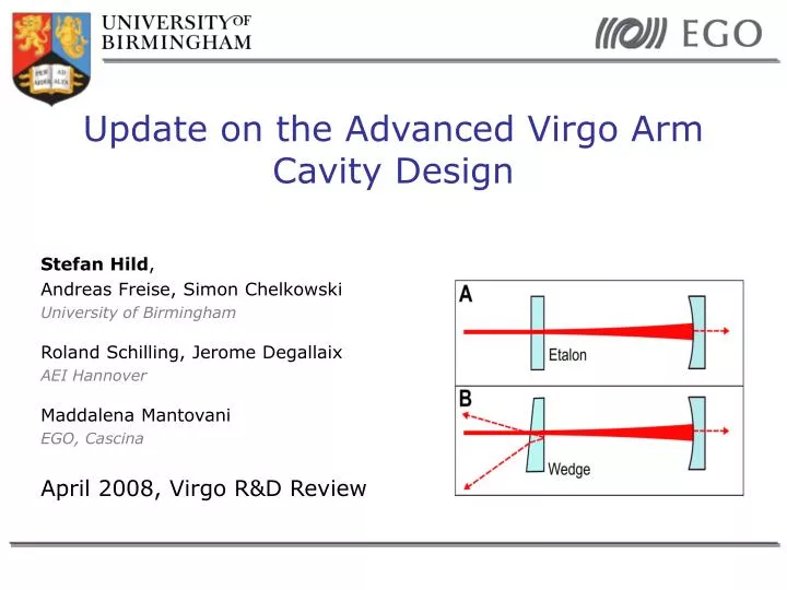
Update on the Advanced Virgo Arm Cavity Design. Stefan Hild , Andreas Freise, Simon Chelkowski University of Birmingham Roland Schilling, Jerome Degallaix AEI Hannover Maddalena Mantovani EGO, Cascina April 2008, Virgo R&D Review. See Maddalenas talks. Overview.

E N D
Update on the Advanced Virgo Arm Cavity Design Stefan Hild, Andreas Freise, Simon Chelkowski University of Birmingham Roland Schilling, Jerome Degallaix AEI Hannover Maddalena Mantovani EGO, Cascina April 2008, Virgo R&D Review
See Maddalenas talks Overview • At January’s Virgo week we presented a new concept for arm cavity design of advanced Virgo (www.sr.bham.ac.uk/~hild/presentations/etalon_vs_wedges.ppt) • The new concept combines advantages of wedges and etalon effect. • What is new since last talk? • Numerical simulations and Analytical approximations • Quantitative evaluation of etalon imperfection • Temperature stability requirement • Influence onto alignment signals • Higher order mode buildup VIRGO R&D review, April 2008
Motivation: Input mirror without wedge • Initial Virgo has no wedges in the input mirrors • The etalon effect could be used for adjusting the cavity finesse (compensating for differential losses) • If etalon effect is not controlled it might cause problems VIRGO R&D review, April 2008
Motivation: Input mirror featuring a wedge • Used by initial LIGO • Reflected beams from AR coating can be separated from main beam => pick-off beams provide additional ports for generation of control signals. • No etalon effect available. VIRGO R&D review, April 2008
IDEA: Wedges at input mirrors and etalon effect at end mirrors • Wedge at input mirrors: • Allows for additional pick-off beams • (Concentrate on compensating thermal lensing in input mirror) • Use etalon effect at end test mass • Replace AR-coating by a coating of about 10% reflectivity. • Ideally use a curved back surface (same curvature as front). • End mirror behaves similarly to flat/flat etalon. VIRGO R&D review, April 2008
What can we gain by using the proposed arm cavity design? • Experience from current detectors: Reflectivities of coatings accurate, but unexplained losses. • We concentrate on the differential losses => Optimal solution: adjusting end mirror transmittance. (Changing the input mirror would also change the amount of directly reflected light) • Several technical noises (such as laser frequency and laser intensity noise) couple proportional to the asymmetry of the arms. • Illustrating example: • 30 ppm differential losses • Using the etalon effect it should be possible to reduce the differential losses to 1 ppm • Reduce the noise coupling by a factor of 30 !! VIRGO R&D review, April 2008
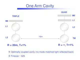
Starting with a single AdV arm cavity • Using a single AdV arm cavity (no IFO). • Parameters used: • IM trans = 0.007 • IM loss = 50 ppm • EM trans = 50 ppm • EM loss = 50 ppm • AR coatings = 0ppm • IM curvature = 1910m • EM curvature = 1910m • Input = 1W • Figure of merrits = intra cavity power or loss compensation or cavity finesse or transmittance of EM. Parameters taken from these 2 documents: VIRGO R&D review, April 2008
Optimal solution: curved Etalon • Examples of figures of merrit: • Transmittance of end mirror (etalon) • Finesse of arm cavity VIRGO R&D review, April 2008
Etalon changes optical phase • When changing the etalon tuning the optical-phase changes as well. (noise!) • The two etalon surfaces build a compound mirror, whose apparent position depends on the etalon tuning. VIRGO R&D review, April 2008
Requirement for temperature stability of etalon substrate • Can calculate require-ment for temperature stability for Advanced Virgo etalon • Using ‘worst case’: 1.22pm/deg • dn/dT = 1.09e-5/K • Substrate thickness = 10cm Example @100Hz: 4e-11K/sqrt(Hz) This requirement is still 2 orders of magnitude above (safer) than temperature stability required from dL/dT of the substrates. VIRGO R&D review, April 2008
Everything fine as long Etalon matches the specs…… but what if not ??=> need to check !! VIRGO R&D review, April 2008
Optical design: Check system integrity for deviations from specs • A deviation in the reflectivity of the etalon coating: • Only changes tuning range (no problem) • A deviation in the relative misalignment (parallelism) and relative curvature of the two etalon surfaces: • Imperfect wave front overlap… • Reduces tuning range … • Beam shape distortions … VIRGO R&D review, April 2008
FFT-simulation of a non-perfect etalon • Using R. Schilling’s WaveProp, (http://www.rzg.mpg.de/~ros/WaveProp/) • Cross checking with DarkF. • Parameters: • Field: 256x256 • Computing 3000 roundtrips • End mirror front: • 50ppm transmission • R_c = 1910m • End mirror back: • Varying three parameters • Reflectance • Misalignment (parallelism) • Curvature VIRGO R&D review, April 2008
Analytic Approximations using Higher-Order Modes • Reflection at a (slightly) misaligned component can be characterised by scattering into higher order TEM modes • This model is valid for misalignments below half the diffraction angle (paraxial approximation) • The amplitude in the outgoing fields is given by coupling coefficients knmnm • For small misalignments the coupling coefficients knmnm can be approximated. The amount of light which remains in a TEM00 mode is given by: (q is the Gaussian beam parameter of the light at the mirror) VIRGO R&D review, April 2008
Misalignment of etalon back surface • Strong influence of relative alignment of etalon surfaces. • Question: What accuracy can state of the art manufacturing provide? • Example: Initial Virgo input mirrors (flat/flat) = 1urad VIRGO R&D review, April 2008
Curvature deviation of etalon back surface • Curvature mismatch has only moderate influence to tuning range of the etalon. VIRGO R&D review, April 2008
Summary • Advanced Virgo CAN feature wedges in the input mirrors AND use the etalon effect at the end mirrors. • Proposed concept allows us to build ‘arm cavities with adjustable losses’. • A curved/curved etalon would be ideal. • Evaluated and quantified the influence of etalon imperfections using numerical simulations and analytical approximations. • Investigations of influence onto alignment signals and higher order mode buildup: See Maddalena’s talk. VIRGO R&D review, April 2008
More details can soon be found in … Outlook Potential issues to be investigated: • Need a control system for etalon tuning (error signal + actuator). • Need a value for the expected differential losses in Advanced Virgo in order to choose the reflectivity of the etalon. VIRGO R&D review, April 2008
E N D VIRGO R&D review, April 2008
Common Mode Rejection Factor • Finesse and losses are coupled. • Probably the differential losses will be the driving element. Finesse assymetry Differential losses Flaminio et al, VIR-NOT-LAP-1390-313 VIRGO R&D review, April 2008