Download
1 / 40
400 likes | 536 Views
EFW Instrument Testing to Date. Michael Ludlam for EFW Team Space Sciences Laboratory University of California, Berkeley. Overview. IDPU Board Testing DCB & FSW LVPS BEB DFB Boom Qualification AXB SPB Instrument Testing IDPU Integration Boom Deployments AC Test / BEB sensor control

E N D
EFW Instrument Testing to Date Michael Ludlam for EFW Team Space Sciences Laboratory University of California, Berkeley
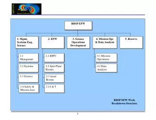
Overview • IDPU Board Testing • DCB & FSW • LVPS • BEB • DFB • Boom Qualification • AXB • SPB • Instrument Testing • IDPU Integration • Boom Deployments • AC Test / BEB sensor control • Noise, Timing, Phasing • Calibration
DCB Testing Both FM DCB boards have completed & passed their board functional test – (RBSP_EFW_DCB_009) Boards have been integrated into IDPU and function correctly with other boards and booms. FSW v3.00 burned into PROMs. Installed on boards. Initially some problems, but failure analysis is pointing towards lead bending procedure. New parts bent correctly both work on flight units. Limited thermal testing was conducted & passed to verify no thermal issues. Other DCB modifications Flash FET switches layout reversed. Rework fix. Addition of inductor to suppress SEE induced transients from MSK regulators. Flight board termination was different than ETU requiring a number of resistor changes.
FSW Status FSW complete. Burned in PROMs after completion of CPT on ETU. All Analyses completed : RBSP_EFW_FSW_004_Analyses.xls Comprehensive Test Report : RBSP_EFW_FSW_020C_CPT_20101212.pdf Code Inspection Report : RBSP_EFW_FSW_021_Inspection.pdf Long Duration Stress Test Report : RBSP_EFW_FSW_022B_LDS_Report.pdf
Summary FSW Development PROM Software Contains all Required Functions EEPROM is empty at this point On-Board Scripts Room Available in PROM No Scripts Defined Verification at the Box & Instrument levels (Not FSW-level) GSE/SOC Flash Memory “MET-to-Block” data management Boom Door Opening & Wire Deployment Real Data Compression (Requires Signals In, SOC to decode) EEPROM test in TVAC
RBSP LVPS Testing (1) LVPS Testing completed on both boards. All functions passed. LVPS Testing is divided into sections • 1- BEB Digital and Analog • 2- IDPU Digital • 3- IDPU Analog • 4- BEB 225V • These four sections have the same topology. The following tests were performed to verify their function individually: • Frequency Adjustment to 187KHz • FET Gate and Drain Waveform Check • Verify Output Voltages • Load Test (half load/ full load/no load) • Output Ripple Measurement • Line Test where S/C Voltage is varied from 24V to 35V • Short Circuit Protection Test where a 1 Ohm resistor load is applied and the circuit recovers from this large load.
RBSP LVPS Testing (2) LVPS Testing completed on both boards. All functions passed. LVPS Testing is divided into sections - section 5: • 5- Floaters • Output Voltage Range • Load tests • Output Ripple Measurement • Line Voltage Test • Short Circuit Protection Test • SYNC test • Verified that all sections are operating at 200KHz when the internal clock is activated • Verified that when an external Clock is applied all sections are synchronized • Verified that internal crystal is turned off when an external clock is applied • Housekeeping • Inrush Current • 40V Survival test
RBSP LVPS testing (3) Power Control Board Testing Reference Voltage is verified Housekeeping Monitor values are verified. Motors, Doors and Stacers Activation verified using a tester that consists of resistors and LEDs Each command was sent separately and the current consumption is recorded.
All Digital Fields Boards Delivered All 3 DFBs delivered to Berkeley All tested and qualified for flight DFBs meet or exceed all performance requirements No known performance deficiencies
DFB Entrance Criteria – All Met All Requirements Verified Release/signature process complete All RFAs closed Deviation or Waivers Completing release/signature process on 1 remaining waiver for PCB bake-out recording. CCB approved 1/3/11. One Part issue in resolution Op-Amp failure analysis in process by APL End-Item-Data Packages completing FM-1 complete and delivered to Berkeley FM-2 & FM-3 waiting on outstanding waiver
Extensive Testing on all DFBs All board-level testing complete on all DFBs per the test plan Tested the full default configuration of each DFB Science data products including: Survey and Burst data from the digital filters, Trigger data, Spectral data, and Cross spectral data Synch to 1 PPS test, super-synch (long and 1sec) Full Analog section testing - 16K ADC sampling Stimulated analog inputs create proper response on the appropriate digital outputs Verified that each digital data product can access all its commandable sources. Obtained calibration data Gains, Offsets, Crosstalk and Noise Characteristics Long duration testing ran on each board 3-4 days each Thermal cycle testing between -25 to +55 on all DFBs No open work remaining on any DFB
BEB Testing The following tests were performed during bench testing of the BEB. DC offset Test DAC and MUX Setting Verification test DC Gain Verification Frequency Response Verification EMFISIS Distortion Test EMFISIS Frequency Response AC Test Line Verification
BEB Example Results All measurements were in specification. More details in Calibration slides. Gain Frequency (Hz)
Boom Qualification • All AXB and SPB units have completed qualification program
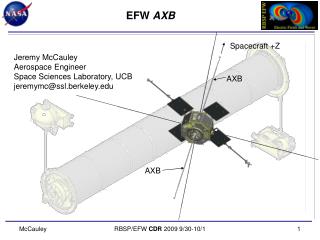
Axial Booms (AXB) Jeremy McCauley Aerospace Engineer Space Sciences Laboratory, UCB jeremymc@ssl.berkeley.edu Spacecraft +Z AXB AXB
EFW AXBEnvironmental Testing Integrate Stacer, Whip and Cage Integrated Vibration Test PER Electrical Functional Test Electrical Functional Test Stacer Mech Functional,Length & Runout Measurement, Continuity Check Whip and Cage Mechanical Functional Dis-Integrate Stacer, Whip and Cage Electrical Functional Test Whip and Cage TV Hot Deploy Whip and Cage TV Cold Deploy Integrate Stacer, Whip and Cage Mass Properties Science Calibration Stacer Mech TV Hot Deploy,Length & Runout Measurement, Continuity Check Stacer Mech TV Hot Deploy,Length & Runout Measurement, Continuity Check PSR
EFW AXBI&T: Deployments Functional Deployments Expected number of deployments on the instrument at launch: 5 Functional (MIP) Post Vibe Functional (“test as you fly” exception) Thermal Vacuum Hot Thermal Vacuum Cold INT Deployment with IDPU and Flight Harness Deployments of Whip and Cage at SC Level after Vibe All stacer deployments include: Frangibolt and Motor trending, EOT Switch verification, Continuity verification, Runout and Stiffness testing.
EFW AXBI&T: Alignment Alignment Testing Runout Requirement: <1° from spin axis
EFW AXBI&T: Vibration Vibration Testing Sine Vibration to flight levels per 7417-9019 Section 5.4.5 Random to GEVS Workmanship Levels per 7417-9019 Section 5.4.5 Self-shock survival from boom deployment actuations ETU First Frequency: X, Y = 180 Hz, Z = 275 Hz FM1 (SN_004) First Frequency: X, Y = 177 Hz, Z = 275 Hz FM1 (SN_005) First Frequency: X, Y = 160 Hz, Z = 295 Hz FM2 (SN_003) First Frequency: X, Y = 166 Hz, Z = 278 Hz FM2 (SN_006) First Frequency: X, Y = 157 Hz, Z = 297 Hz
EFW AXBI&T: TV Thermal Vacuum Testing 4(6) operational cycles plus 1 survival cycle, per the requirements and limits indicated in 7417-9019 section 5.3.2 Deployment tests at hot and cold levels HOT TURN ON HOT DEPLOY N COLD TURN ON COLD DEPLOY
EFW AXBMass Properties Testing Mass: 2.97 predict, 3.40 NTE
EFW AXBHYPOT Testing HYPOT Testing: Connectors need testing for resistance to High Potential (HI POT) Not reasonable on a part by part basis Individual representative components passed Harness tested in unit Whip Hinge Whip Harness Sphere
EFW AXBStatus Harness Passed HyPot Testing Mechanisms Passed Vibration Mechanisms Passed Thermal Vacuum Mass Properties Testing Completed INT Deploys completed SN_004 will be tested again with updated Frangibolt AXB ready for INT Environments
Instrument Testing Instrument Testing All IDPU boards have been integrated into IDPU boxes. Functional testing mostly occurs at the instrument level. Most testing is to do with instrument performance. Boom Deployments have been conducted with Flight IDPU/ Flight Boom Units on all booms. AC Test / BEB sensor control tests complete. Verification of HSK complete. Noise, Timing, Phasing, ‘Full Up’, Calibration to be discussed by John Bonnell.
RBSP EFW LVPS LVPS Problem Failure Reports There were 8 PFRs and 15 Engineering Change Notices. Problem Failure Reports PFR 022: IC leads were cut to fit the pads. MRB approved PFR 025: L4, L7 have pads that are too small for the magnetic wire. The wires are connected to the leads of capacitors. MRB approved PFR 038: Floater Magnetics assembly error. The magnetic wire was connected to a via. No damage occurred. FM1 only. MRB approved PFR 030: Floater Voltages were out of range. Magnetics are re-wound using ‘balanced winding’. ECN 047 is generated. MRB approved. PFR 037: C59 reversed capacitor. No damage occurs. The capacitor is replaced. FM1 only. MRB approved. PFR 040: Adjusting IDPU Analog Output Voltages. ECN 045 is generated. MRB approved. PFR 049: On board crystal did not turn off when the external clock from DCB is applied. ECN 056 is generated. Added a diode in the SYNC circuit. MRB approved. PFR 055: When an external clock is applied to LVPS the signal looked distorted. Changing the feedback transformer ratio fixed this distortion. As precaution we changed U30 (NOR gate IC). FM2 was fixed before turn on. U30 is not replaced on FM2. ECN 060 is generated.
RBSP EFW LVPS Engineering Change Notices In order to capture BOM changes that did not cause any Problem Failure Reports we generated ECNs. Previous slide mentioned the ECNs that were generated for specific PFRs. LVPS ECNs ECN 046: Changing the voltage housekeeping resistor dividers to have 2.0V at the output ECN 054: Added 1K resistors between grounds per systems request ECN 055: Assigning MSK resistor and capacitor values post systems tests. These were TBD items before. ECN 057: Changing a resistor value to match ETU. ECN 061: Decreasing BEB Digital output voltage. When an external clock is applied BEB digital output voltage increases. Systems decided that if it is easy to decrease the output voltage then it is better to have voltage less than 5.35V. ECN 062: During Derating Analysis we found a 50V ceramic capacitor. It is changed to a 100V ceramic capacitor. ECN 063: Requirements change on 3.6V Digital output. Increase 3.6V digital output voltage per systems engineering request.
DFB Changes Since CDR Requirements Clarifications Added SuperPPS for synching low rate data FPGA Resource Constraints Removed Solitary Wave Detector Reduce spectral channels from 8 to 7 All science requirements still met