ACARE Brazing Presentation
ACARE Brazing Presentation. “The Art & Science of Brazing”. Instructor: Harold Nelson. Always Remember, Safety is #1 and Everyone’s Business!. ACARE Brazing Presentation. PERSONAL PROTECTIVE EQUIPMENT. Always wear shaded safety glasses with UV filter with at least a number 2 shade rating


ACARE Brazing Presentation
E N D
Presentation Transcript
ACARE Brazing Presentation “The Art & Science of Brazing” Instructor: Harold Nelson
Always Remember, Safety is #1 and Everyone’s Business! ACARE Brazing Presentation
PERSONAL PROTECTIVE EQUIPMENT • Always wear shaded safety glasses with UV filter with at least a number 2 shade rating • Operators must not wear garments made of synthetic fibers. • Hair below the collar should be tied back during brazing operations. • Heat and flame resistant gloves must be worn at all times. • Heat and flame resistant brazing sleeves with wrist protection must be worn at all times.
BRAZING SAFETY • NEVER use matches or a cigarette lighter to light a torch. • Keep your torch in front of you and under control at all times. • Check hoses, fittings and tanks for fuel gas and oxygen leaks regularly. • Keep flammable materials away from brazing areas. • Turn off torches when not in use and place them in the designated location.
TANK USAGE AND STORAGE • Fuel gas and oxygen cylinders (storage bottles) must always be handled with extreme care and be property secured. The most common means to secure them is by chaining them in place. • ALWAYS vent or bleed off a small amount of gas or oxygen from a cylinder before attaching a regulator. This blows any dirt or dust off the cylinder valve. • ALWAYS bleed off pressure from hoses and regulators when not in use. • ALWAYS light the fuel gas first during set-up. This prevents back pressuring the fuel line with higher-pressure oxygen.
EQUIPMENT • Fixtures for holding parts in correct alignment while brazing (Where applicable). • Access to nitrogen or other inert gas to be used as a purge gas to prevent internal oxidation. • Brush for applying flux (Where applicable). • Heat sinks or heat shields. • A striker for lighting the pilot or torch. • Clean hot water (Where required) for removing flux residue and oxidation. • A tip cleaner for cleaning tips. • Safety equipment.
Equipment Maintenance & Inspection • Check hoses and fittings for wear, leaks and damage. • Check the orifices in brazing tips to be sure they are not plugged. • Glass covers must be checked for cracks and damage to assure legible readings on the dials and that they are working properly.
Equipment Set-up • Turn on the fuel gas and oxygen supply valves. • Turn the fuel gas regulator handle. • Turn the oxygen regulator handle. • Light the torch using the striker. • Now slowly open the oxygen valve on the torch. You will need to make proper adjustments to the flame depending on • flame condition. You will do this by adjusting the fuel and oxygen valves to achieve the correct brazing flame. • A neutral flame is best for most copper brazing. Avoid excessively oxidizing flames. A reducing flame is best for joints containing steel.
Equipment Shutdown • Turn off the fuel gas and oxygen supply valves. • Relieve all pressure from the torch, hoses and regulators. Wait until both gauges read zero and the pilot is out. • Turn off both valves on the torch body.
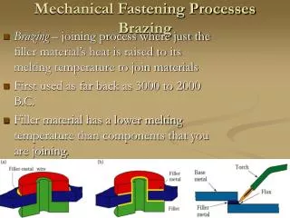
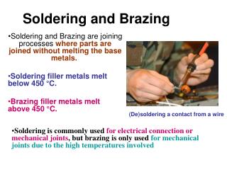
BRAZE PROCESS • A properly brazed joint is obtained by capillary action, which evenly pulls the molten filler metal into the joint. • A well designed joint will facilitate good brazing, but will not guarantee a good joint unless correct procedures are followed.
BRAZE PROCESS The following six basic steps to insure they are producing a quality joint every time.
BRAZE PROCESS • STEP 1 - GOOD FIT & PROPER CLEARANCE • STEP 2 - CLEANLINESS OF PARTS • STEP 3 - ASSEMBLE AND SUPPORT BRAZE JOINTS • STEP 4 - APPLYING FLUX TO JOINT SURFACES • STEP 5 - BRAZING THE ASSEMBLY • STEP 6 - CLEANING OF BRAZE JOINTS & FLUX REMOVAL
Step 1: GOOD FIT & PROPER CLEARANCE • To obtain capillary action. Capillary action is the force that pulls or draws the molten filler metal into the joint. • Strength of the joint. A proper fit will produce a strong joint capable of withstanding the stresses of pressure, thermal expansion and contraction and vibration without failure. • Economy. A well-fitted joint will enable the brazer to produce a quality braze joint in the least amount of time without using more filler metal than necessary. • Make sure the tubing is free of burrs. Burrs could prevent the tube from seating properly, and could also be a problem in the refrigeration system if they break loose inside the assembly.
Step 1: GOOD FIT & PROPER CLEARANCE • Connect the tube ends to check the fit: The clearance between the inner and outer part should be.002" to.005" at room temperature and .001" to .005" at brazing temperature for copper-to-copper joints. An “easy slip fit” will make a sound joint if correct procedures are followed. Too much clearance reduces the capillary action and retards the flow of the filler metal. Proper clearance with a thin film of filler metal will produce a leak free joint with high strength.
Step 2: CLEANLINESS OF PARTS • Capillary action will work only when the surfaces of metal are clean. • Oil and grease will carbonize when heated; forming a film over which molten filler metal will not flow. • After the parts have been cleaned they must be dry and they should be used as soon as possible to prevent recontamination. • Check the inside of the tubes for oxidation, this contaminate can become dislodged and can cause failure of the refrigeration system.
Step 2: CLEANLINESS OF PARTS Clean vs. Dirty Parts
Step 3: ASSEMBLE AND SUPPORT BRAZE JOINT • Parts must be assembled so that joints have a straight, uniform appearance after insertion. • Fixtures should be built to allow the brazer to manipulate assembly to always have Vertical Down Brazing. • Nitrogen or another inert gas purge must be used during the brazing process to ensure internal cleanliness. Nitrogen flowing through tubing during brazing displaces oxygen preventing the formation of oxides on the inside of the tube assemblies.
Step 3: ASSEMBLE AND SUPPORT BRAZE JOINT • Nitrogen Set Up • Attach a nitrogen gas hose to the fixture. • Turn on the nitrogen gas regulator and adjust to the proper flow rate. • Verify that there are no restrictions and that nitrogen is flowing freely by checking the exit end of the assembly, unit circuit or coil with a small flame such as a lighter or other suitable method. • If flow is not detected, do not braze the assembly.
Step 3: ASSEMBLE AND SUPPORT BRAZE JOINT • Sensitive parts such as valves and solenoids must be protected during brazing. • - Examples for protecting them are chill blocks, water-cooled fixtures and heat sinks. • - The most common heat sink is a wet rag. A wet rag wrapped on a valve during brazing will absorb much of the heat preventing damage to the valve. • Heat Shielding should be applied to sensitive areas such as wires and insulation.
Step 4: APPLYING FLUX TO JOINT SURFACES (if needed) • Flux is a chemical compound applied to the joint surfaces before brazing. • Flux on the joint area will shield the surfaces from the air, preventing oxides from forming. • Flux will also dissolve and absorb oxides that form during heating or that were not completely removed during the cleaning process. FLUX IS NOT FOR CLEANING PARTS. • Flux is applied to promote the flow and bonding of the filler metal to the base metals throughout the joint being brazed.
Step 4: APPLYING FLUX TO JOINT SURFACES (if needed) • When joining copper to copper with copper- phosphorus alloy filter metal, paste flux is NOT necessary because the phosphorus in the alloy acts as the flux to remove oxides. • (If an alloy with no phosphorus were being used, flux would be necessary even to join copper to copper.) • Flux is necessary when joining dissimilar metal combination such as copper to brass or copper to steel or for repair purposes.
Step 4: APPLYING FLUX TO JOINT SURFACES (if needed) Flux can act as a temperature indicator letting the brazer know when the base metal is just about hot enough to melt the brazing filler metal.
Step 4: APPLYING FLUX TO JOINT SURFACES (if needed) • The flux will bubble as the water boils off. (212° F) • Then the flux will become white & puffy. • (600° F)
Step 4: APPLYING FLUX TO JOINT SURFACES (if needed) • The flux begins to lay flat against the metal surface and has a milky appearance. (800°F)
Step 4: APPLYING FLUX TO JOINT SURFACES (if needed) • When the flux becomes clear, it is an indication that the metal is hot enough to flow the filler alloy. ( 1100° F)
Step 5: BRAZING THE ASSEMBLY • Always use nitrogen to purge the assembly for brazing. Allow sufficient time for nitrogen to purge the part (size and flow dependent). A 20 – 25 SCFH (Standard Cubic Feet per Hour) flow is recommended during brazing. • Protect Sensitive parts such as valves and insulation from excessive heat. When brazing near a valve, insulation, or other braze joints, isolate or protect them from heat to prevent damage or leaks by using heat sinks, water, wet rags or heat shields. Heat sinks and shields should be called out on drawings and process sheets.
Step 5: BRAZING THE ASSEMBLY • Prevents oxides from forming during the brazing operation. • All tubing must be purged with nitrogen during the brazing process.
Step 5: BRAZING THE ASSEMBLY Flowmeter
Step 5: BRAZING THE ASSEMBLY • Low-pressure nitrogen gas must be flowing through the copper lines when brazing to eliminate scale and oxidation that can cause blockage in a system. • A flowmeter works in conjunction with a regulator to accurately calibrate the outlet pressure while monitoring the flow of gas. • A regulator an be adjusted to deliver low pressure, but by itself, the regulator won’t tell you the nitrogen is flowing. • The flowmeter has a float ball that rises in the flowmeter tube indicating low pressure flow of nitrogen when purging copper lines.
Step 5: BRAZING THE ASSEMBLY • Selection of the proper brazing filler material for the joint you are brazing is extremely important. There are a great many filler metals and it is up to engineering to choose the correct alloy for the metals and assembly conditions. • Normally a phosphorus or “phos” - copper rod with 0 % silver is used for joining copper to copper without the use of paste. This is due to the ability of the phosphorus in the alloy to act as a flux.
Step 5: BRAZING THE ASSEMBLY • A 5 % phos-copper alloy can be used on looser fitting joints, repair work, tacking and bridging gaps. Loose fitting joints with excessive clearances should be redesigned or have the manufacturing process corrected ASAP. The 5% alloy is only a temporary help until the process or drawing is modified. • Do not use filler metals containing phosphorus to braze ferrous metals, such as steel, because the joint will be brittle and will fail in a short period of time.
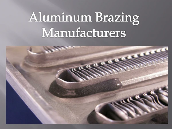
Step 5: BRAZING THE ASSEMBLY Joining similar metals - Heat the male portion of the tube and then the Female end that the male is inserted into and allow the joint to melt the alloy.
Step 5: BRAZING THE ASSEMBLY Dissimilar Metals - Heat the good conductor then heat the poor conductor then allow the joint to melt the alloy.
Step 5: BRAZING THE ASSEMBLY When copper or brass turns a dull red or pink, brazing temperature has been reached. If copper is cherry red or orange it is overheated.
Step 5: BRAZING THE ASSEMBLY 3. Sweep the torch between the tube and coupling on all joint sides. This will help bring both parts to brazing temperature.
Step 5: BRAZING THE ASSEMBLY 4. Move the flame to the coupling base. Molten brazing filler metal will flow towards the heat. Directing the flame to the coupling promotes flow into the joint.
Step 5: BRAZING THE ASSEMBLY 5. Apply the filler metal only when both parts have reached brazing temperature. (The flame may be briefly deflected to the filler metal end to begin the melting process). As tube diameter increases you will need to apply filler metal at several points around the tube circumference to ensure complete joint fill.