Download
1 / 25
410 likes | 1.25k Views
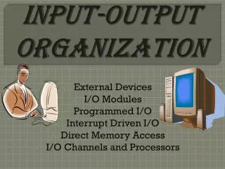
INPUT-OUTPUT ORGANIZATION. Peripheral Devices Input-Output Interface Asynchronous Data Transfer Modes of Transfer Priority Interrupt Direct Memory Access Input-Output Processor Serial Communication. Peripheral Devices. PERIPHERAL DEVICES. Input Devices. Output Devices.

E N D
INPUT-OUTPUT ORGANIZATION • Peripheral Devices • Input-Output Interface • Asynchronous Data Transfer • Modes of Transfer • Priority Interrupt • Direct Memory Access • Input-Output Processor • Serial Communication
Peripheral Devices PERIPHERAL DEVICES Input Devices Output Devices • Keyboard • Optical input devices • - Card Reader • - Paper Tape Reader • - Bar code reader • - Digitizer • - Optical Mark Reader • Magnetic Input Devices • - Magnetic Stripe Reader • Screen Input Devices • - Touch Screen • - Light Pen • - Mouse • Analog Input Devices • Card Puncher, Paper Tape Puncher • CRT • Printer (Impact, Ink Jet, • Laser, Dot Matrix) • Plotter • Analog • Voice
Input/Output Interfaces INPUT/OUTPUT INTERFACES * Provides a method for transferring information between internal storage (such as memory and CPU registers) and external I/O devices * Resolves the differences between the computer and peripheral devices - Peripherals - Electromechanical Devices CPU or Memory - Electronic Device - Data Transfer Rate Peripherals - Usually slower CPU or Memory - Usually faster than peripherals Some kinds of Synchronization mechanism may be needed - Unit of Information Peripherals - Byte CPU or Memory - Word - Operating Modes Peripherals - Asynchronous CPU or Memory - Synchronous
Input/Output Interfaces I/O BUS AND INTERFACE MODULES I/O bus Data Processor Address Control • Interface Modules : (VLSI Chip) • PCI • IDE • SATA • RS-232 • USB Interface Interface Interface Interface Keyboard Magnetic Magnetic and Printer disk tape display terminal Each peripheral has an interface module associated with it Interface - Decodes the device address (device code) - Decodes the commands (operation) - Provides signals for the peripheral controller - Synchronizes the data flow and supervises the transfer rate between peripheral and CPU or Memory • I/O command (Function codes) : • Control Command • Status Command • Input Command • Output Command
Input/Output Interfaces I/O BUS AND MEMORY BUS Functions of Buses • * MEMORY BUS is for information transfers between CPU and the MM • * I/O BUS is for information transfers between CPU • and I/O devices through their I/O interface • * Some computers use a common single bus system • for both memory and I/O interface units • - Use one common bus but separate control lines for each function • - Use one common bus with common control lines for both functions • * Some computer systems use two separate buses, • one to communicate with memory and the other with I/O interfaces Physical Organizations
I/O Bus versus Memory Bus 1) Use two separate buses, one for memory and the other for I/O : I/O Processor is required (IOP) 2) Use one common bus for both memory and I/O but have separate control lines for each : Isolated I/O IN, OUT : I/O Instruction MOV or LD : Memory read/write Instruction 3) Use one common bus for memory and I/O with common control lines : Memory Mapped I/O MOV or LD : I/O and Memory read/write Instruction Intel, Zilog * Control Lines I/O Request, Mem Request, Read/Write Motorola * Control Lines Read/Write
Input/Output Interfaces ISOLATED vs MEMORY MAPPED I/O Isolated I/O - Separate I/O read/write control lines in addition to memory read/write control lines - Separate (isolated) memory and I/O address spaces - Distinct input and output instructions Memory-mapped I/O • - A single set of read/write control lines • (no distinction between memory and I/O transfer) • - Memory and I/O addresses share the common address space • -> reduces memory address range available • - No specific input or output instruction • -> The same memory reference instructions can • be used for I/O transfers • - Considerable flexibility in handling I/O operations
Input/Output Interfaces I/O INTERFACE I/O data Port A register Bidirectional Bus data bus buffers I/O data Port B register I/O Device CPU Chip select CS Internal bus Register select Control Control RS1 Timing register Register select and RS0 Control I/O read RD Status Status I/O write register WR • Example of I/O Interface : • 4 I/O port : Data port A, Data port B, Control, Status • Address Decode : CS, RS1, RS0 CS RS1 RS0 Register selected 0 x x None - data bus in high-impedence 1 0 0 Port A register 1 0 1 Port B register 1 1 0 Control register 1 1 1 Status register Programmable Interface - Information in each port can be assigned a meaning depending on the mode of operation of the I/O device -> Port A = Data; Port B = Command; Port C = Status - CPU initializes(loads) each port by transferring a byte to the Control Register -> Allows CPU to define the mode of operation of each port (In, Out, Command, …) -> Programmable Port: By changing the bits in the control register, it is possible to change the interface characteristics
Asynchronous Data Transfer ASYNCHRONOUS DATA TRANSFER Synchronous and Asynchronous Operations Asynchronous Data Transfer Synchronous - All devices derive the timing information from common clock line Asynchronous - No common clock Asynchronous data transfer between two independent units requires that control signalsbe transmitted between the communicating units to indicate the time at which data is being transmitted Two Asynchronous Data Transfer Methods Strobe pulse - A strobe pulse is supplied by one unit to indicate the other unit when the transfer has to occur Handshaking - A control signal is accompanied with each data being transmitted to indicate the presence of data - The receiving unit responds with another control signal to acknowledge receipt of the data
Asynchronous Data Transfer STROBE CONTROL * The strobe may be activated by either the source or the destination unit Source-Initiated Strobe for Data Transfer Destination-Initiated Strobe for Data Transfer Block Diagram Block Diagram Data bus Data bus Source Destination Source Destination unit unit unit unit Strobe Strobe Timing Diagram Timing Diagram Valid data Valid data Data Data Strobe Strobe
Asynchronous Data Transfer HANDSHAKING Strobe Methods Source-Initiated The source unit that initiates the transfer has no way of knowing whether the destination unit has actually received data Destination-Initiated The destination unit that initiates the transfer no way of knowing whether the source has actually placed the data on the bus To solve this problem, the HANDSHAKE method introduces a second control signal to provide a Reply to the unit that initiates the transfer
Asynchronous Data Transfer SOURCE-INITIATED TRANSFER USING HANDSHAKE Data bus Source Data valid Destination Block Diagram unit unit Data accepted Valid data Data bus Timing Diagram Data valid Data accepted Sequence of Events Destination unit Source unit Place data on bus. Enable data valid. Accept data from bus. Enable data accepted Disable data valid. Invalidate data on bus. Disable data accepted. Ready to accept data (initial state). * Allows arbitrary delays from one state to the next * Permits each unit to respond at its own data transfer rate * The rate of transfer is determined by the slower unit
Asynchronous Data Transfer DESTINATION-INITIATED TRANSFER USING HANDSHAKE Data bus Block Diagram Source Data valid Destination unit unit Ready for data Timing Diagram Ready for data Data valid Valid data Data bus Sequence of Events Destination unit Source unit Ready to accept data. Enable ready for data. Place data on bus. Enable data valid. Accept data from bus. Disable ready for data. Disable data valid. Invalidate data on bus (initial state). * Handshaking provides a high degree of flexibility and reliability because the successful completion of a data transfer relies on active participation by both units * If one unit is faulty, data transfer will not be completed -> Can be detected by means of a timeout mechanism
Asynchronous Data Transfer ASYNCHRONOUS SERIAL TRANSFER Four Different Types of Transfer Asynchronous Serial Transfer - Employs special bits which are inserted at both ends of the character code - Each character consists of three parts; Start bit; Data bits; Stop bits. 1 1 0 0 0 1 0 1 Stop Start Character bits bit (1 bit) bits (at least 1 bit) A character can be detected by the receiver from the knowledge of 4 rules; - When data are not being sent, the line is kept in the 1-state (idle state) - The initiation of a character transmission is detected by a Start Bit , which is always a 0 - The character bits always follow the Start Bit - After the last character , a Stop Bit is detected when the line returns to the 1-state for at least 1 bit time The receiver knows in advance the transfer rate of the bits and the number of information bits to expect
Modes of Transfer • The final target of I/O data is memory of the system • Memory data transfer to and from peripherals • 1) Programmed I/O • 2) Interrupt-initiated I/O • 3) Direct Memory Access (DMA) • 4) I/O Processor (IOP) • Example of Programmed I/O • Interrupt-initiated I/O • 1) Non-vectored : fixed branch address • 2) Vectored : interrupt source supplies the branch address (interrupt vector)
Priority Interrupt • Priority Interrupt • Identify the source of the interrupt when several sources will request service simultaneously • Determine which condition is to be serviced first when two or more requests arrive simultaneously • 1) Software : Polling • 2) Hardware : Daisy chain, Parallel priority
“1” “1” “0” • Polling • Identify the highest-priority source by software means • One common branch address is used for all interrupts • Program polls the interrupt sources in sequence • The highest-priority source is tested first • Polling priority interrupt • If there are many interrupt sources, the time required to poll them can exceed the time available to service the I/O device • Daisy-Chaining : Device 2 Interrupt Request
INTACK INT • One stage of the daisy-chain priority arrangement : No interrupt request Invalid : interrupt request, but no acknowledge No interrupt request : Pass to other device (other device requested interrupt ) Interrupt request
Parallel Priority • Priority Encoder • Interrupt Enable F/F (IEN) : set or cleared by the program • Interrupt Status F/F (IST) : set or cleared by the encoder output • Priority Encoder Truth Table • Interrupt Cycle • At the end of each instruction cycle, CPU checks IEN and IST • if both IEN and IST equal to “1” • CPU goes to an Instruction Cycle • Sequence of microoperation during Instruction Cycle : Decrement stack point : Push PC into stack : Enable INTACK : Transfer VAD to PC : Disable further interrupts Branch to ISR
Software Routines KBD Int. Here 749 DISK Int. Here 255
Initial Operation of ISR • 1) Clear lower-level mask register bit • 2) Clear interrupt status bit IST • 3) Save contents of processor registers • 4) Set interrupt enable bit IEN • 5) Proceed with service routine • Final Operation of ISR • 1) Clear interrupt enable bit IEN • 2) Restore contents of processor registers • 3) Clear the bit in the interrupt register belonging to the source that has been serviced • 4) Set lower-level priority bits in the mask register • 5) Restore return address into PC and set IEN • Direct Memory Access (DMA) • DMA • DMA controller takes over the buses to manage the transfer directly between the I/O device and memory
DMA Transfer (I/O to Memory) • 1) I/O Device sends a DMA request • 2) DMAC activates the BR line • 3) CPU responds with BG line • 4) DMAC sends a DMA acknowledge to the I/O device • 5) I/O device puts a word in the data bus (for memory write) • 6) DMAC write a data to the address specified by Address register • 7) Decrement Word count register • 8) if Word count register = 0 EOT interrupt • 9) if Word count register 0 DMAC checks the DMA request from I/O device
Transfer Modes • 1) Burst transfer : • 2) Cycle stealing transfer : • DMA Controller ( Intel 8237 DMAC ) • DMA Initialization Process • 1) Set Address register : • memory address for read/write • 2) Set Word count register : • the number of words to transfer • 3) Set transfer mode : • read/write, • burst/cycle stealing, • I/O to I/O, • I/O to Memory, • ….. • 4) DMA transfer start • 5) EOT (End of Transfer) • Interrupt
Input-Output Processor (IOP) • IOP : • Communicate directly with all I/O devices • Fetch and execute its own instruction • IOP instructions are specifically designed to facilitate I/O transfer • DMA Controller (DMAC) must be set up entirely by the CPU • Designed to handle the details of I/O processing • Command • Instructionthat are read from memory by an IOP • Distinguish from instructions that are read by the CPU • Commands are prepared by experienced programmers and are stored in memory • Command word = IOP program
CPU - IOP Communication : • Memory units acts as a message center : • each processor leaves information for the other Message Center IOP Program CPU Program