
Remote Sensing and Image Processing: 5
E N D
Presentation Transcript
Remote Sensing and Image Processing: 5 Dr. Mathias (Mat) Disney UCL Geography Office: 301, 3rd Floor, Chandler House Tel: 7670 4290 (x24290) Email: mdisney@geog.ucl.ac.uk www.geog.ucl.ac.uk/~mdisney
EMR arriving at Earth • We now know how EMR spectrum is distributed • Radiant energy arriving at Earth’s surface • NOT blackbody, but close • This lecture….. • Interactions of EMR with atmosphere • scattering • Atmospheric windows and choosing the “right” place for bands • Interactions at the surface • Scattering and angular effects
Departure from blackbody assumption • Interaction with gases in the atmosphere • attenuation of solar radiation
R R 2 1 target target R 4 R 3 target target Interactions with the atmosphere • Notice that target reflectance is a function of • Atmospheric irradiance • reflectance outside target scattered into path • diffuse atmospheric irradiance • multiple-scattered surface-atmosphere interactions From: http://www.geog.ucl.ac.uk/~mdisney/phd.bak/final_version/final_pdf/chapter2a.pdf
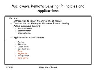
Interactions with the atmosphere: scattering • Caused by presence of particles (soot, salt, etc.) and/or large gas molecules present in the atmosphere • Interact with EMR and cause to be redirected from original path. • Scattering amount depends on: • of radiation • abundance of particles or gases • distance the radiation travels through the atmosphere (path length) After: http://www.ccrs.nrcan.gc.ca/ccrs/learn/tutorials/fundam/chapter1/chapter1_4_e.html
Atmospheric scattering 1: Rayleigh • Particle size << of radiation • e.g. very fine soot and dust or N2, O2 molecules • Rayleigh scattering dominates shorter and in upper atmos. • i.e. Longer scattered less (visible red scattered less than blue ) • Hence during day, visible blue tend to dominate (shorter path length) • Longer path length at sunrise/sunset so proportionally more visible blue scattered out of path so sky tends to look more red • Even more so if dust in upper atmosphere • http://www.spc.noaa.gov/publications/corfidi/sunset/ • http://www.nws.noaa.gov/om/educ/activit/bluesky.htm After: http://www.ccrs.nrcan.gc.ca/ccrs/learn/tutorials/fundam/chapter1/chapter1_4_e.html
Atmospheric scattering 2: Mie • Particle size of radiation • e.g. dust, pollen, smoke and water vapour • Affects longer than Rayleigh, BUT weak dependence on • Mostly in the lower portions of the atmosphere • larger particles are more abundant • dominates when cloud conditions are overcast • i.e. large amount of water vapour (mist, cloud, fog) results in almost totally diffuse illumination After: http://www.ccrs.nrcan.gc.ca/ccrs/learn/tutorials/fundam/chapter1/chapter1_4_e.html
Atmospheric scattering 3: Non-selective • Particle size >> of radiation • e.g. Water droplets and larger dust particles, • All affected about equally (hence name!) • Hence results in fog, mist, clouds etc. appearing white • white = equal scattering of red, green and blue s After: http://www.ccrs.nrcan.gc.ca/ccrs/learn/tutorials/fundam/chapter1/chapter1_4_e.html
Atmospheric absorption • Other major interaction with signal • Gaseous molecules in atmosphere can absorb photons at various • depends on vibrational modes of molecules • Very dependent on • Main components are: • CO2, water vapour and ozone (O3) • Also CH4 .... • O3 absorbs shorter i.e. protects us from UV radiation
Landsat TM bands in atmospheric windows Atmospheric “windows” • As a result of strong dependence of absorption • Some totally unsuitable for remote sensing as most radiation absorbed
Atmospheric “windows” • If you want to look at surface • Look in atmospheric windows where transmissions high • BUT if you want to look at atmosphere ....pick gaps • Very important when selecting instrument channels • Note atmosphere nearly transparent in wave i.e. can see through clouds! • BIG advantage of wave remote sensing
Atmospheric “windows” • Vivisble + NIR part of the spectrum • windows, roughly: 400-750, 800-1000, 1150-1300, 1500-1600, 2100-2250nm
Recap • Signal we measure contains atmospheric “contamination” (or information depending on your point of view!) • Rayleigh (fine dust and gases), Mie (bigger particles) and non-selective scattering (water vapour and the rest) • Perform atmospheric correction to get at surface signal • Part of pre-processing steps (see later) • So what happens at the surface?
Natural surfaces somewhere in between Reflectance • When EMR hits target (surface) • Range of surface reflectance behaviour • perfect specular (mirror-like) - incidence angle = exitance angle • perfectly diffuse (Lambertian) - same reflectance in all directions independent of illumination angle) From http://www.ccrs.nrcan.gc.ca/ccrs/learn/tutorials/fundam/chapter1/chapter1_5_e.html
Surface energy budget • Total amount of radiant flux per wavelength incident on surface, () Wm-1 is summation of: • reflected r, transmitted t, and absorbed, a • i.e. () = r + t + a • So need to know about surface reflectance, transmittance and absorptance • Measured RS signal is combination of all 3 components After: Jensen, J. (2000) Remote sensing of the environment: an Earth Resources Perspective.
(a) (b) (c) (d) Figure 2.1 Four examples of surface reflectance: (a) Lambertian reflectance (b) non-Lambertian (directional) reflectance (c) specular (mirror-like) reflectance (d) retro-reflection peak (hotspot). Angular distribution of reflectance • Real surfaces usually display some degree of reflectance ANISOTROPY • Lambertian surface is isotropic by definition • Most surfaces have some level of anisotropy • Described by Bidirectional Reflectance Distribution Function (BRDF) From: http://www.geog.ucl.ac.uk/~mdisney/phd.bak/final_version/final_pdf/chapter2a.pdf
Features of BRDF • Bowl shape • increased scattering due to increased path length through canopy
Features of BRDF • Bowl shape • increased scattering due to increased path length through canopy
Features of BRDF • Hot Spot • mainly shadowing minimum • so reflectance higher
Directional reflectance: BRDF • Good explanation of BRDF: • http://geography.bu.edu/brdf/brdfexpl.html
Summary • Top-of-atmosphere (TOA) signal is NOT target signal • function of target reflectance • plus atmospheric component (scattering, absorption) • need to choose appropriate regions (atmospheric windows) • Surface reflectance is anisotropic • i.e. looks different in different directions • described by BRDF • angular signal contains information on size, shape and distribution of objects on surface