Download
1 / 27
270 likes | 459 Views
Design and Implementation of a Fast -S teering Secondary Mirror System. Maryfe Culiat Trex Enterprises July 25, 2007. Overview. Benefits of a fast-steering secondary mirror (FSSM) FSSM system diagram Optical bench set-up Actuator analysis System parameters and implementation of design.

E N D
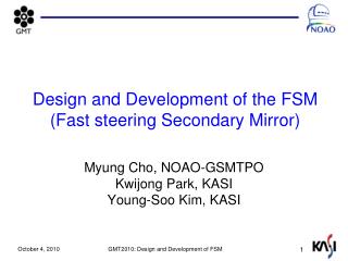
Design and Implementation of a Fast-Steering Secondary Mirror System MaryfeCuliat Trex Enterprises July 25, 2007
Overview • Benefits of a fast-steering secondary mirror (FSSM) • FSSM system diagram • Optical bench set-up • Actuator analysis • System parameters and implementation of design
Conventional fast-steering mirror technologyis placed downstream from telescope • Atmospheric turbulence and mechanical jitter results in the loss of resolution in imagery • Adaptive optics needed for correction • Microscopic: Deformable mirror • Macroscopic: Fast-steering mirror • Tip-tilt easiest to correct, yet provides substantial return in image quality FSM
Why use fast-steering mirrors at the secondary mirror position? • Advanced technologies such as ultra light-weighted SiC allow for FSSM • Benefits of having a fast-steering secondary mirror: 1. Tilt correction at the secondary keeps FSM close-coupled to the pupil 2. Simplified adaptive optics system; eliminates need for a pupil relay 3. Reduces need for another mirror surface FSSM
Goals • Understand closed-loop FSSM system • Hands-on hardware integration • Actuator trade study • Obtain product information from vendors • Using system parameters, down-select from vendor products
Overview • Benefits of a fast-steering secondary mirror (FSSM) • FSSM system diagram • Optical bench set-up • System parameters • Implementation of design • Summary
A fast-steering secondary can provide rapid tip/tilt correction for line-of-sight stabilization Fast Steering Secondary Mirror Tracker Camera Position Sensors Actuators Drive Electronics, Position Sensor Module Computer Read camera Read FSSM position Offset coordinate transformation Command actuator Position Sensors Actuators
A fast steering secondary can provide rapid tip/tilt correction for line-of-sight stabilization Fast Steering Secondary Mirror Tracker Camera Position Sensors Actuators Drive electronics, Position Sensor Module Computer Read camera Read FSSM position Offset coordinate transformation Command actuator Position Sensors Actuators
Overview • Benefits of a fast-steering secondary mirror (FSSM) • FSSM system diagram • Optical bench set-up • Actuator analysis • System parameters and implementation of design
Spare fast-steering mirror allows for better understanding of closed-loop system Fast steering mirror Actuators Position sensors Quad cell Computer Drive electronics
Integration of FSSM components • Tilt range of +/- 3mrad • Small-signal bandwidth: ~ 200-300 Hz • Full stroke bandwidth: ~ 30-40 Hz
Overview • Benefits of a fast-steering secondary mirror (FSSM) • FSSM system diagram • Optical bench set-up • Actuator analysis • System parameters and implementation of design
Two types of actuators are used in fast-steering mirror applications • Piezoelectric actuators • Voice coil actuators Source: www.pi.ws, Physik Instrumente Source: www.beikimco.com, BEI Kimco Magnetics
Piezoelectric actuators are preferred over voice coil actuators for this application Based on comparable products from BEI Kimco and Physik Instrumente
Overview • Benefits of a fast-steering secondary mirror (FSSM) • FSSM system diagram • Optical bench set-up • Actuator analysis • System parameters and implementation of design
Vendor products can be narrowed down given system parameters Parameters given: • Mirror tilt range of at least ±2mrad • SiC mirror – allows for reactionless • Tripod drive Source: www.pi.ws, Physik Instrumente Source: S. Walton
PhysikInstrumente’s P-843.60 fulfills performance specifications • P-843.60 • 3 actuators = $8,895 Source: www.pi.ws, Physik Instrumente Source: www.pi.ws, Physik Instrumente • 90 µm stroke • 1.8 nm resolution • Integrated position sensor
Integrated strain gauge sensors offer high resolution and bandwidth • Resistive film bonded to piezo stack • Sub-nanometer resolution • Low heat generation • Indirect metrology Source: www.pi.ws, Physik Instrumente
Drive electronics are integrated into a single package Drive electronics: $16,025 • E-500, chassis w/ voltage supply = $2,327 • E-505, amplifier = $6,687 • E-509.S3, SGS module = $3,075 • E-516.I3, display module = $3,936 Source: www.pi.ws, Physik Instrumente
Continuation of design includes finite element analysis • Interface between mirror and actuators; mounting details of flexures
Conclusion • Fast-steering secondary mirror technology allows for simplified adaptive optics system • Piezoelectric actuators fulfill requirements for this application • Continued analysis of system includes interface between mirror and actuators
Acknowledgements Riki Maeda, Dennis Douglas, Daron Nishimoto • Steve Walton • Rich Holmes • Don Bruns • J.D. Armstrong Hilary O’Bryan, Scott Seagroves, Lisa Hunter James Deichmann, Jason Wong This work has been supported by the National Science Foundation Science and Technology Center for Adaptive Optics, managed by the University of California at Santa Cruz under cooperative agreement No. AST - 9876783.
Flexible tips • M5 threading • 20mm length • Tilting angle of +/- 0.5 degrees • Bending stiffness of 22 nm/rad • 3 flexures = $459
Raw calculation of actuator stroke Assuming movement of only one actuator: Distance of actuator from center of mirror, x Θ Θ, maximum tilt angle Actuator stroke, y
Calculation of loaded resonant frequency fo = resonant frequency of unloaded actuator (Hz) fo = 6 kHz kT = piezo actuator stiffness (N/m) kT = 107 N/m meff = effective mass (kg) meff = 3.5 g m’eff = additional mass M + meff m’eff = 88.5 g f’o, Loaded resonant frequency ≈ 1293 Hz Maximum operating frequency ≈ 431 Hz Equations source: www.pi.ws
Tracker camera • FLIR SC6000 • InGaAs detector (near-IR) • Resolution: 320 x 256