Download
1 / 24
300 likes | 560 Views
Point-to-Multipoint Advantage. With W i Rake. September 2009. W i Rake Introduction. W i Rake – Professional Wireless Broadband Infrastructure Solution Cost-effective and scalable multi-service platform that supports both backhaul and business-grade access applications.

E N D
Point-to-MultipointAdvantage With WiRake September 2009 www.hypercable.fr
WiRake Introduction WiRake – Professional Wireless Broadband Infrastructure Solution • Cost-effective and scalable multi-service platform that supports both backhaul and business-grade access applications Designed for high performance and reliability in real world environments Delivers: • Robust OFDM • Unmatched Range & Capacity • Extreme Reliability & Flexibility • Industry-Leading Low Latency • Ease of Deployment, Use & Management • 5.4GHz and 5.8GHz Band Operation • Point-to-point and Point-to-Multipoint Configurations M/M/D/S Hypercable s.a.r.l.
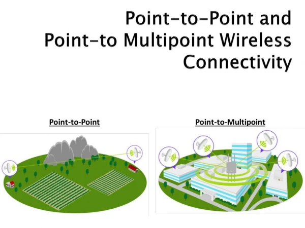
Why Point to Multipoint? • WHY PMP? • Save spectrum – uses only one 5.4 GHz or 5.8 GHz channel • Save hardware, installation Costs and tower space • Directly link multiple sites over a single layer 2 network • Cover wide areas for nomadic applications • Single point of management M/M/D/S Hypercable s.a.r.l.
Unique Features of Wirake PMP • Highest capacity PMP in the industry • Lowest Latency • Fastest system registration time for nomadic applications • Ideal for Business Grade Access, • Large Campus Networks and Multipoint Backhaul M/M/D/S Hypercable s.a.r.l.
Competitive Positioning High Data Rate 40+Mbps/Sector Low Latency Multipoint Backhaul WiRake Medium Data Rate <30Mbps/Sector Medium Latency Business Access Application Performance VL C….. T….. A….. B…….. Low Data Rate <20Mbps/Sector High Latency Residential Access M/M/D/S Hypercable s.a.r.l..
WiRake PMP Vertical Markets Enterprise & Municipality networks Fixed & nomadic WiFi Backhaul AN-80i Wirake WISP with business grade services Security networks M/M/D/S Hypercable s.a.r.l.
PMP Deployments Idaho Department of Energy • PMP configuration supporting building, vehicles, and trailers • 4 base stations – 4 sectors per station • Covering 900 square miles • Connecting all DoE facilities – 5,000 employees sharing critical, confidential information • Delivering nomadic services • Supports video, voice, e-mail, web High throughput, Large Campus, Nomadic M/M/D/S Hypercable s.a.r.l.
PMP Deployments Lewis & Clark County (Montana, USA) • 4 access points / 16 subscribers • Combination of point-to-multipoint (PMP) and point-to-point (PTP) links running human resource, fleet management, financial and email/data applications • Distances of more than 7.5 miles • Average speeds of 36 to 48 Mbps • Savings: 10’s of thousands per year High throughput, Multipoint backhaul M/M/D/S Hypercable s.a.r.l.
PMP Deployments London to Brighton Commuter Route (UK) • Approximately 80 km • Highly cluttered urban environment • 160 Km per hour trains • Offered by T-Mobile • Technology by WiRake and Nomad Digital • Average data rate exceeds > 6 Mbps • Passengers connect by WiFi • Connection to 35 trackside basestations • No tall towers used High speed, high data rate, nomadic WiFi backhaul M/M/D/S Hypercable s.a.r.l.
PMP Deployments • Michael Anderson – President: PDQlink, Leland Illinois, Suburban WISP • Internet connection is at the base station • NOC is attached to a subscriber station • Over 20 servers at the NOC including Part-15.org and WISPCON • Carries 1,000,000 messages per month • “Co-locates very well” Stealth Wirake antennas co-locates with a wide variety of other 5.8 GHz gear with 5-15 feet away • Longer link, about 15 miles High throughput, Business Access M/M/D/S Hypercable s.a.r.l.
Multiple Service Flows on the Same Subscriber Unit • For each subscriber unit • Different applications get different priority Example: Voice + Data • Each has guaranteed CIR provision for QoS Co. A Voice AN-80i SW1 Co. A Data SS1 Site 2 Internet Router AN-80i SC Site 1 Co. A Voice Co. A Data M/M/D/S Hypercable s.a.r.l.
Virtual Private LAN Scenario • Company A is connected to other Company A sites • Company B traffic is segregated and gets its own QoS AN-80i Co. A SW1 SS1 Co. A Site 2 Internet Router AN-80i SC Site 1 Co. A AN-80i Co. B SW2 SS2 Co. B Site 3 M/M/D/S Hypercable s.a.r.l.
Equipment Management via VLAN • Remote management • User defined VLAN group for equipment • Management traffic is isolated and secure User Network AN-80i User Network SW1 SS1 Site 2 Internet Router AN-80i SC User Network Site 1 AN-80i User Network SW2 SS2 Site 3 NMS M/M/D/S Hypercable s.a.r.l.
VLAN Network Benefits • Extend private network across WAN • Partition a LAN based on functional requirements • Increase network performance • Improve network manageability • Relieve physical topology dependency • Enhance network security Subscriber Stations SS VLAN1 Sector Controller SC VLAN2 Internet ATM/MPLS VLAN4 VLAN1 VLAN2 VLAN3 Subscriber Stations VLAN3 M/M/D/S Hypercable s.a.r.l.
VLAN Operator Benefits • Faster network ROI • Able to serve multiple clients on a common infrastructure • Lower network Capex • Able to fine tune network for higher efficiency • Lower network Opex • Able to simplify network topology for manageability • Wider range of services • Able to fit QoS levels to user app requirements • Higher network security • Able to partition user and management traffic flows M/M/D/S Hypercable s.a.r.l.
WiRake AN-80i Speeds and Feeds PMP: Basic Speeds and Feeds • Up to 20 active subscriber stations per sector • Max 12 CIR connections per subscriber station • Sample max. LOS range: • 6.5 km with 90 degree sector antennas, • 64QAM2/3 modulation • 22 km with 90 degree sector antennas, • 16QAM1/2 modulation M/M/D/S Hypercable s.a.r.l.
WiRake AN-80i PMP Highlights • IEEE 802.1Q standard compliant • Multiple VLAN connections per subscriber station • User defined CIR bandwidth allocation for each connection • Virtual private LAN services based on VLAN ID classification • Virtual group and VPLS across multiple subscribers • Per group subscriber-to-subscriber multicast/broadcast control • VLAN for equipment management traffic M/M/D/S Hypercable s.a.r.l.
Configuring a PMP System Connection Link VLAN capable switch Dept 1 AN-80i Dept 2 SS1 SW1 Site 2 Group AN-80i Router SC VLAN capable switch Site 1 Dept 2 AN-80i Dept 1 SW2 SS2 Site 3 Create Connection Create Link Create Group M/M/D/S Hypercable s.a.r.l.
Link-Group-Connection • Link – wireless link • Wireless path between one SC and one SS • SS MAC address • DL burst rate, UL burst rate • Group – logical, multicast domain • Made up of SS connections assigned to the group • How packets of this group gets treated at SC Ethernet port • Tagged or untagged at SC • What QoS level is assigned for the group’s multicast traffic • Connection – logical user data flow between SC and SS • A connection belongs to a group and a link • What QoS level is assigned to this connection • How packets of this connection are treated at SS Ethernet port • Tagged or untagged at SS
Configuration Limits • Max # of active SS’s per sector is 20 • Max # of groups per sector is 30 • Max # of connections (VIDs) per link is 12 • Max # of MAC addresses per group is 4000 • Max # of IDs (link, group, connection) per sector is 1000 • Each connection (VID) must belong to one group and one group only • Each connection (VID) must belong to one link and one link only • Each group can have only one connection (VID) at a subscriber or section controller • A pass-through group is used to pass “untagged packets” and “tagged, but undefined” packets • There can be only one pass-through group at a SC • There can be only one pass-through connection at a SS • QoS level setting – provision as per PMP Config Tool for CIR/capacity planning M/M/D/S Hypercable s.a.r.l.
VPN Service Scenario • For each site • Individual service provisions for different companies and different applications • Each has guaranteed CIR provision for QoS • Voice packets tagged with VID= 300 • Data packets tagged with VID= 400 VLAN Capable switch • Co. A voice packets tagged with VID= 50 • Co. A data packets tagged with VID= 55 • Co. B voice packets tagged with VID= 80 • Co. B data packets tagged with VID= 85 Co. A Voice AN-80i SW1 Co. A Data SS1 Site 2 Internet Router AN-80i VLAN capable switch SC Site 1 Co. B Voice AN-80i • Four Groups, one for each VLAN Co. B Data Co. B Data SW2 SS2 Co. A Voice • Voice packets tagged with VID= 600 • Data packets tagged with VID= 700 Site 3 Co. B Voice Co. A Data M/M/D/S Hypercable s.a.r.l.
Virtual Private LAN Scenario • For Company A • Seamless VLAN connectivity for a mix of .1Q aware and unaware LANs • Internet access through Router • For Company B • Q-in-Q VLAN trunking service to remote site • Packets at Site 1 untagged VLAN unaware switch AN-80i Co. A • Co. A packets tagged with VID=50 • Co. B packets tagged with VID=80 SW1 SS1 Co. A Site 2 Internet Router AN-80i VLAN capable switch SC Site 1 Co. A AN-80i • All Co. A connections set to Group I • All Co. B connections set to Group II Co. B SW2 SS2 Co. B • Co. A packets tagged with VID=300 • Co. B packets tagged with VID=700 Site 3 M/M/D/S Hypercable s.a.r.l.
Campus Network Scenario • Dept 1 packets tagged with VID= 300 • Dept 2 packets tagged with VID= 400 • Between Subscriber (SS1) and Switch (SW1) • Each VLAN segment is assigned a unique VID • E.g. Dept 1 packets are tagged w/ VID=300 • Each VID has a CIR (minimum bit rate) • For each VLAN segment • A virtual group is defined as a multicast domain • E.g. Group I for Dept 1 at Site 1 and Site 2 • Each group has a multicast CIR • Within each virtual group • VID can differ at each site • E.g. Group II for Dept 2 • packet VID=400 at Site 1 • packet VID=700 at Site 2 • Data between Dept 1 & 2 • Through Router • Layer 3 connectivity only VLAN capable switch Dept 1 AN-80i Dept 2 SW1 SS1 Site 2 Router AN-80i VLAN capable switch SC Site 1 Dept 2 AN-80i • All Dept 1 connections set to Group I • All Dept 2 connections set to Group II Dept 1 SW2 SS2 • Dept 1 packets tagged with VID= 300 • Dept 2 packets tagged with VID= 700 Site 3 M/M/D/S Hypercable s.a.r.l.
Mgmt traffic tagged with VID=100 • Mgmt traffic tagged with VID=100 • Mgmt traffic tagged with VID=100 Equipment Management via VLAN • Remote management • User defined VLAN group for equipment • Isolated, secure traffic for AN-80i and/or 3rd party systems VLAN capable switch User Network AN-80i User Network SW1 SS1 Site 1 Site 3 Internet Router AN-80i NMS2 VLAN capable switch SC User Network AN-80i • All mgmt connections set to Group M User Network SW2 SS2 Site 2 NMS1 M/M/D/S Hypercable s.a.r.l.