Increasing Throughput in Component Manufacturing
May 2000. Increasing Throughput in Component Manufacturing. Agenda. The Test Process The Test Procedure The Test Program The Network Analyzer Designing for Manufacturing Summary Appendices. The Test Process The test process encompasses all elements of the test activity.


Increasing Throughput in Component Manufacturing
E N D
Presentation Transcript
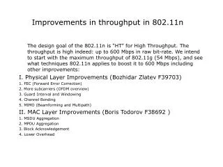
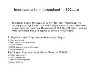
May 2000 Increasing Throughput in Component Manufacturing
Agenda • The Test Process • The Test Procedure • The Test Program • The Network Analyzer • Designing for Manufacturing • Summary • Appendices
The Test ProcessThe test process encompasses all elements of the test activity • Product Design for Testability • Test Requirements Definition • Test Equipment Selection • DUT-to-Test Equipment Interface • Test Procedure design • Test Program Development & Implementation • Test Results Data Processing & Analysis • Test System Maintenance
Test Process Test Procedure Test Program Network Analyzer Calibration Test Set Fixturing Material Handling DUT What Is Involved In Testing
Identify Where are You Spending Your Test Time Failure Analysis/re-work Time 17% Connection Time 20% Data Transfer Time 7% Measurement Setup Time 23% Tuning/Adjustment Time 26% Measurement Sweep Time 7%
Agenda • The Test Process • The Test Procedure • The Test Program • The Network Analyzer • Designing for Manufacturing • Summary • Appendices
Performance Verification and Fault Detection Test Equipment Requirements DUT to Test Equipment Interface Alignment and Adjustments Manual Operator Actions Test Procedure Design Issues Test Process Test Procedure Test Program Network Analyzer Calibration Test Set Fixturing Material Handling DUT
Test Procedure Optimization • Minimize number of tests • Order necessary tests to achieve maximum efficiency • Minimize manual operator actions • Minimize tuning and alignment
Test Procedure Optimization Minimize number of tests • Select the minimum number of tests required to verify DUT performance. • Include tests to detect probable failure modes. • Exclude tests or only test samples for highly unlikely failure modes. • Eliminate test redundancies by considering previously tested failure modes.
Test Procedure Optimization Order necessary tests to achieve maximum efficiency • Order tests that cover most likely failure modes first • Order tests according to failure mode coverage • Group tests to make use of common setup • Minimize setup changes (RF relays, etc.) • Minimize analyzer state/cal changes
Test Procedure Optimization Minimize manual operator actions • Group multiple manual actions into single operator action where possible • Rely on automated measurements and failure mode assumptions where possible
Design automatic adjustment circuitry into device itself Use external computer and a tuning algorithm Pre-screen or match components to minimize the tuning necessary Test Procedure Optimization Minimize manual tuning and alignment
Agenda • The Test Process • The Test Procedure • The Test Program • Internal Automation • External Automation • The Network Analyzer • Designing for Manufacturing • Summary • Appendices
Test Program The test program may reside in the analyzer or on an external computer Test Process Test Procedure Test Program Network Analyzer Calibration Test Set Fixturing Material Handling DUT
Quickly Changing Instrument States For the fastest recall time, keep recalled state as simple as possible: • One channel instead of two • No calibration if possible • No limit lines or limit testing • Turn off display, if possible
Internal Automation • Examples of internal automation: • IBASIC • Test sequencing • Barcode readers • Footswitch (fast - recall)
Agenda • The Test Process • The Test Procedure • The Test Program • Internal Automation • External Automation • The Network Analyzer • Designing for Manufacturing • Summary • Appendices
Interfacing Instruments to the Outside World GPIB LAN Parallel Serial
Pick format Use fastest data transfer mode available Transfer minimum amount of data needed Consider performing error correction externally Improving Data Transfer Speed
Textual Languages Visual Basic (VB), Visual C++, LabWindows/CVI, C/C++, etc. Most flexible Visual Basic and LabWindows/CVI provide for the most rapid Windows development of this group Visual Basic and Visual C++ include database tools for direct database support External AutomationWindows-Based Test Development Software With HP8753 If iBand <> iBandSel Then ' ---- Recall band state --- .RegisterRecall (iBandSel + 1) .Channel = 1 iBand = iBandSel Port = 1 End If .SweepTrig = "SING" If .MeasFormat <> "Log Mag" Then .MeasFormat = "Log Mag" End If If .Smoothing Then .Smoothing = False End If End With ' ------ Read trace data -------- bDready = Get_TraceData(dTraceData()) bDataValid(iBandSel, iGraphType) = bDready Call Extract_FreqData(iBandSel, iGraphType)
Graphical Languages Agilent VEE, LabVIEW, etc. Modular programming targeted to instrument control Generally faster development than textual languages Many existing instrument drivers are available Generally easier to learn than textual languages External AutomationWindows-Based Test Development Software
External AutomationTest Program Design The operator interface should be as simple and intuitive as possible
External AutomationTest Program Design • Minimize the number of operator actions and decisions • Utilize a bar code reader or other automated method to input data • Utilize a database (or file) keyed to the DUT to store and recall all test and instrument parameters
External AutomationTest Program Design Instrument Calibration:Include the calibration procedure in the test program to reduce operator actions
External AutomationTest Program Design • Where practical, store calibration for later recall • A program timer can be utilized to force a new calibration when required
External AutomationMinimize Measurement Time • Group measurements with common test setup conditions • Retrieve trace data and utilize the computer to calculate the required measurement rather than retrieving marker data • Use binary data format (rather than ASCII) for retrieving and sending trace data • Use a single sweep for all trace measurements of the same device setup
Log measurement data to a database for the most utility and flexibility Use database located on a network server to collect data from multipletest stations Use database to analyze test results show trends, match components, etc. External AutomationData Logging
Agenda • The Test Process • The Test Procedure • The Test Program • The Network Analyzer • Maximizing Capabilities • Reducing Tuning Time • Reducing Connection Time • Measurement Uncertainty and Calibration Issues • Designing for Manufacturing • Summary • Appendices
Calibration Maximizing Capabilities Maximize Instrument Sweep Speed Test Process Test Procedure Test Program Network Analyzer Test Set Fixturing Material Handling DUT
Data calculation and formatting Display update Band switches Retrace Sweep and data acquisition (This is the number provided by the network analyzer and is the number quoted in the case study) Sweep Time Vs. Cycle TimeComponents of Cycle Time
Test only over the necessary frequency range Test using fewest frequency points needed Test using the widest IF BW that will provide acceptable performance The Basics of Increasing Network Analyzer Sweep Speed
Optimum Frequency Range Sweep Time: 88 ms Preset Frequency Range Sweep Time: 153 ms Select the Narrowest Frequency Range Needed
21 Measurement Points Sweep Time: 28 ms 801 Measurement Points Sweep Time: 348 ms Choose the Minimum Number of Measurement Points Necessary
Use the Widest IF Bandwidth Possible 4000 Hz IF BW Sweep Time: 88 ms 250 Hz IF BW Sweep Time: 1.5 s
Measuring High-Rejection Devices ~130 dB of rejection
4000 Hz IF BW, no averaging: 88 ms 250 Hz IF BW, no averaging: 1.5 s 4000 Hz IF BW, no averaging: 88 ms 4000 Hz IF BW, 16 averages: 1.4 s IF Bandwidth, Averaging & Dynamic Range Figure A Figure B
Source Power & Dynamic Range Source Power: -20 dBm Source Power: +7 dBm
R Channel Jumper Special Test Sets Designed to Speed Measurement of High-Rejection Devices Source Source Transfer switch Transfer switch R R A B A B Receivers Receivers Port 1 Port 2 Typical standard test set configuration Test set allowing direct receiver access
Special Test Sets Designed to Speed Measurement of High-Rejection Devices Source Source Transfer switch Transfer switch R R A B A B Receivers Receivers R Channel Juniper Port 1 Port 2 Typical standard test set configuration Test set with port 2 coupler reversed
Chopped mode Alternate mode Alternate Sweep Mode for More Dynamic Range
Enhanced Sweep Features Segment 3: 29 ms (108 points, -10 dBm, 6000 Hz) CH1 S log MAG 12 dB/ REF 0 dB 21 PRm Swept-list sweep: 349 ms Linear sweep: 676 ms (201 pts., variable BW's & power) (201 pts., 300 Hz, -10 dBm) Segment 5: 129 ms Segment 1: 87 ms (38 points, +10 dBm, 300 Hz) (25 points, +10 dBm, 300 Hz) START 525.000 000 MHz STOP 1 275.000 000 MHz Segments 2,4: 52 ms No specs here, so no points No specs here, so no points (15 points, +10 dBm, 300 Hz) measured in this span measured in this span
Agenda • The Test Process • The Test Procedure • The Test Program • The Network Analyzer • Maximizing Capabilities • Reducing Tuning Time • Reducing Connection Time • Measurement Uncertainty and Calibration Issues • Designing for Manufacturing • Summary • Appendices
8753ES (201 points, full two-port cal) ~121 ms 8753D (201 points, full two-port cal) ~510 ms Tuning is More Difficult on Slower Analyzers
Fast Two-Port Mode makes multiple forward sweeps for each reverse sweep making component tuning more responsive Use Fast Two-Port Mode to “Speed Up” Slower Analyzers
Response of Properly Tuned Filter Time Domain Filter Tuning Time Domain Frequency Domain
Filter with Resonator 3 Mistuned Time Domain Filter Tuning (Cont'd) Time Domain Frequency Domain
Photo courtesy of Kawasaki Automated Tuning Examples may include: • Robotic arms tuning adjustment screws on a filter • Dremel tool grinding ceramic filter
Agenda • The Test Process • The Test Procedure • The Test Program • The Network Analyzer • Maximizing Capabilities • Reducing Tuning Time • Reducing Connection Time • Measurement Uncertainty and Calibration Issues • Designing for Manufacturing • Summary • Appendices