Download
1 / 28
280 likes | 490 Views
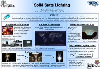
Quantum Dot Phosphors for Solid-State Lighting Devices. A Report of Preliminary Results Charles P. Gibson, University of Wisconsin Oshkosh. Why Should We be Interested in SSL ?. In the US, 22% of electricity is consumed for lighting. This costs about $50 billion per year.

E N D
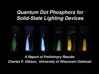
Quantum Dot Phosphors for Solid-State Lighting Devices A Report of Preliminary Results Charles P. Gibson, University of Wisconsin Oshkosh
Why Should We be Interested in SSL ? • In the US, 22% of electricity is consumed for lighting. This costs about $50 billion per year. • High efficiency (>50%) solid-state lighting devices could save up to $42 billion per year. Incandescent efficiency ~ 5% Fluorescent ~ 20% Solid-State (LED) Currently 15 - 30% But could be >50% !
Most SSL Devices Use Light Emitting Diodes. • LEDs are made from inorganic semiconductors. • They contain a p-doped and an n-doped layer. • Application of an electrical bias produces holes (+) and electrons (-). • Recombination of electrons and holes produces light. • Monochromatic light emitted. • Phosphors can be used to create white light. DOE: Basic Research Needs for Solid State Lighting
Most White LEDs Combine Blue and Yellow. • Blue LEDs are used. Some blue light escapes. • Some blue light is captured by a phosphor and is down-converted to yellow. • The combined blue and yellow emission appears to be white. http://www.yfrindia.com/articles/misc/a0098.html
But Color Rendering is a Problem. 485 nm diffuse sunlight 485 nm • Sunlight: High relative intensity across the entire visible region, with a peak in the blue-green region. (CRI = 100) • White LEDs: Narrow blue peak, with broad yellow peak; low intensity in the blue-green region. (CRI ~75) www.mvlc.com
Conventional Approach for Improving CRI. colors. • Use more… • Use assorted LEDs – overly complicated? • Include more phosphors – phosphor development? New Phosphors JNIMS - 2008 Blue LED -SiAlON:Eu CaAlSiN3:Eu 400 nm 500 nm 600 nm 700 nm 800 nm Japan NIMS: 55th Meeting Japan Soc. Applied Physics (2008) http://techon.nikkeibp.co.jp/english/
Alternative Approach: Direct-White Phosphor. • A direct-white phosphor is a single material that emits high-quality white light. • A direct-white phosphor should very broad emission across entire visible region. • A direct-white phosphor should have max in the blue-green region of the spectrum (475 – 525 nm). • Suitable direct-white phosphors for SSL are not available. They need to be developed. Goal: Develop Suitable Direct-White Phosphors.
How About ZnS Quantum Dot Phosphors ? • Desired: Should emit when exposed to near UV light. • ZnS (bulk):Band gap ~3.5 eV ( 350 nm). • ZnS (QD): Maybe. May depend on size, composition. • Desired: Good UV-A visible quantum efficiency. • ZnS (bulk): P22-B ~ 65%; others may be better. • ZnS (QD): Maybe. May depend on size, composition. • Desired: maxin the blue-green region (475 – 525 nm). • ZnS (bulk): True for many phosphors. • ZnS (QD): Maybe. May depend on size, composition.
How About ZnS Quantum Dot Phosphors ? • Desired: Broad emission, across entire visible range. • ZnS (bulk):Emission bands tend to be rather narrow. • ZnS (QD): Maybe. May depend on size, polydispersity. • Desired: Relatively cheap and easy to make. • ZnS (bulk): Yes. • ZnS (QD): Yes, using arrested precipitation methods. • Desired: Nontoxic. • ZnS (bulk): Relatively nontoxic. • ZnS (QD): Should be relatively nontoxic. (Much less toxic than CdE quantum dots.)
Target Material: Capped ZnS Quantum Dots. Zn salt Mix 1) Purify Activator 2) Cap capped ZnS (QD) phosphor capped ZnS (QD) ZnS (QD) Uncapped QDs Capped QDs Phosphor S source (aq)
First Step: Make Uncapped ZnS QDs. Zn salt Mix 1) Purify Activator 2) Cap capped ZnS (QD) phosphor capped ZnS (QD) ZnS (QD) Uncapped QDs Capped QDs Phosphor S source (aq)
Characterization of Uncapped QDs. • X-ray diffraction confirms ZnS is the product. • Scherrer broadening: ave particle size is ca. 3 – 8 nm. 3 nm ZnS Relative intensity 20 30 40 50 60 70 80 100 90 No emission when irradiated with UV-A (365 nm).
Second Step: Cap the ZnS QDs. Zn salt Mix 1) Purify Activator 2) Cap capped ZnS (QD) phosphor capped ZnS (QD) ZnS (QD) Uncapped QDs Capped QDs Phosphor S source (aq)
● ● ● ● ● ● ● ● ● ● ● ● ● ● ● ● ● ● ● ● ● ● ● ● ● ● ● ● ● ● ● ● ● ● ● ● ● ● ● ● ● ● ● ● ● ● ● ● ● ● ● ● ● ● ● ● ● ● ● ● ● ● ● ● Strategy for Capping the Quantum Dots. x x x x ZnS (QD) x x x x - H2S ZnS (QD) + x x O (spacer) X C x x OH x x x x X is a coordinating atom or group
Characterization of Capped QDs. • X-ray diffraction confirms ZnS is the product. • Thermal analysis consistent with monolayer coverage. • XRD and TEM confirm quantum dot size (3 – 8 nm). 5 nm 50 nm No emission when irradiated with UV-A (365 nm).
Third Step: Add Activator. Zn salt Mix 1) Purify Activator 2) Cap capped ZnS (QD) phosphor capped ZnS (QD) ZnS (QD) Uncapped QDs Capped QDs Phosphor S source (aq)
● ● ● ● ● ● ● ● ● ● ● ● ● ● ● ● ● ● ● ● ● ● ● ● ● ● ● ● ● ● ● ● ● ● ● ● ● ● ● ● ● ● ● ● ● ● ● ● ● ● ● ● ● ● ● ● ● ● ● ● ● ● ● ● Third Step: Add Activator. x x x x x x Capped ZnS (QD) x x + ZnS (QD) x x x x MLn x x MLn Activator x x
Characterization of Phosphors. • X-ray diffraction confirms ZnS is the product. • XRD and TEM confirm quantum dot size (3 – 8 nm). • Thermal analysis consistent with monolayer coverage. • 0 • Final products glow when irradiated 365 nm. max of emission depends on activator.
Several of the Phosphors are Direct White. 460 nm • max ranges from 440 nm to 500 nm. (Target: 475 – 525 nm.) • Very broad emission in the visible region. • Assymetric peak. (Tail at longer .) • Quantum yield ~10% (No self-absorp. corr.) • No attempt to improve quantum yield. 400 600 nm 500 ZnS(QD):Zn
Emission of ZnS(QD):Zn. • max = 460 nm. Broad peak with tail at longer . • Emission resembles diffuse sunlight in the visible region of the spectrum (400 – 650 nm). 460 nm 485 nm 400 400 600 nm 600 nm 500 500 ZnS(QD):Zn diffuse sunlight
Color Coordinates of ZnS(QD):Zn. • CIE Color coordinates of: direct overhead sunlight: 0.35x, 0.35y • CIE Color coordinates of: ZnS(QD):Zn: 0.29x, 0.33y • CIE Color coordinates of: north sky daylight: 0.30x, 0.31y http://hyperphysics.phy-astr.gsu.edu/hbase/vision/cie.html
Shifting Emission to longer . • Emission can be shifted to longer max by adding Cd2+ as an activator. This gives yellow phosphors. max = 530 542 570 nm ZnS(QD):Cd • max depends on the amount of Cd2+ added.
Conclusions. • We have developed new ZnS quantum dot phosphors. They are relatively cheap and easy to make. • Some of these are direct-white phosphors. When irradiated with UV-A (365 nm), these phoshors have very broad emission. Some of these have max in or close to the desired target range (475 – 525 nm). • The quantum yield for emission of the white phosphors is about 10%. No attempt has been made to optimize quantum yield. • Using Cd2+ as a activator shifts emission to longer wavelength.
Future Work. • Evaluate different capping ligands. Variables: • Length; • Degree of conjugation; • Coordinating groups. • Evaluate different activator. Variables: • Identity of activator; • Amount; • Mixed activators. Example - ZnS(QD):Zn,Cd • Use off the shelf UV-LEDs to construct prototype white SSL devices.
Quantum Dot Phosphors for Solid-State Lighting Devices Preliminary Results: Charles Gibson, UW-Oshkosh Support for this project provided by: UWS-Applied Research Grant Program.
● ● ● ● ● ● ● ● ● ● ● ● ● ● ● ● ● ● ● ● ● ● ● ● ● ● ● ● ● ● ● ● ● ● ● ● ● ● ● ● ● ● ● ● ● ● ● ● ● ● ● ● ● ● ● ● ● ● ● ● ● ● ● ● Alternative Embodiment: Transition Layers. The capped/activated quantum dot may include a transition layer of a different semiconductor. x x x x Transition layer in green e.g., ZnO x x x x ZnS (QD) x x x x MLn x x x x
● ● ● ● ● ● ● ● ● ● ● ● ● ● ● ● ● ● ● ● ● ● ● ● ● ● ● ● ● ● ● ● ● ● ● ● ● ● ● ● ● ● ● ● ● ● ● ● ● ● ● ● ● ● ● ● ● ● ● ● ● ● ● ● ● ● ● ● ● ● ● ● ● ● ● ● ● ● ● ● ● ● ● ● ● ● ● ● ● ● ● ● ● ● ● ● ● ● ● ● ● ● ● ● ● ● ● ● ● ● ● ● ● ● ● ● ● ● ● ● ● ● ● ● ● ● ● ● Alternative Embodiment: Bridged QDs. x x x x Two or more capped quantum dots may bind to the activator x x x x x x x x ZnS (QD) x x x MLn x x x x x ZnS (QD) x x x x x x x x x x x x
Alternative Embodiment: Bridged QDs. This could result in the formation of oligomers, or 1- 2- or 3-dimensional polymeric networks. Capped QD Capped QD Capped QD MLn MLn MLn x