Integrated Gasification Combined Cycles
350 likes | 534 Views
Integrated Gasification Combined Cycles. P M V Subbarao Professor Mechanical Engineering Department. Go Slow with Irreversible Process…. The Combustion. Integrated Gasification Combined Cycle.

Integrated Gasification Combined Cycles
E N D
Presentation Transcript
Integrated Gasification Combined Cycles P M V Subbarao Professor Mechanical Engineering Department Go Slow with Irreversible Process…. The Combustion..
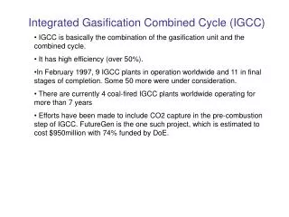
Integrated Gasification Combined Cycle • Integrated Gasification Combined Cycle (IGCC) is emerging as a best available technology to utilize low quality or contaminated energy resources, coal or oil. • It can meet emission limits not achievable by other conventional or advanced competing technologies. • In particular IGCC offers refiners the possibility of reducing to zero the production of residual fuel oil, an increasingly undesired product, while at the same time, co-producing electricity, hydrogen and steam. • It also drastically cuts SO2 emissions.
Basic Structure of IGCC N2 Air
IGCC is a capital-intensive technology. Therefore, to exploit with maximum profit all the advantages of this technology, it is important to optimize the design to improve performance and reduce capital cost. One important design aspect is the degree of integration between the gas turbine and the air separation unit. The choice of the optimum degree of integration can bring substantial benefits in performance efficiency and capital outlay. The selection of the best degree of integration to assure the maximum profitability of IGCC. The need of clean energy technologies has been in existence since the first oil crisis more than 25 years ago. IGCC is emerging today as one of the most promising technologies to exploit low-quality solid and liquid fuels and meet the most stringent emission limits. Critical Factors for Selection of IGCC
How does IGCC work? • IGCC is a combination of two leading technologies. • The first technology is called coal gasification, which uses coal to create a clean-burning gas (syngas). • The second technology is called combined-cycle, which is the most efficient method of producing electricity commercially available today. • Coal Gasification: • The gasification portion of the IGCC plant produces a clean coal gas (syngas) which fuels the combustion turbine. • Coal is combined with oxygen in the gasifier to produce the gaseous fuel, mainly hydrogen and carbon monoxide. • The gas is then cleaned by a gas cleanup process. • After cleaning, the coal gas is used in the combustion turbine to produce electricity.
Coal Gasification • As early as 1800, coal gas was made by heating coal in the absence of air. • Coal gas is rich in CH4 and gives off up to 20.5 kJ per liter of gas burned. • Coal gas or town gas, as it was also known became so popular that most major cities and many small towns had a local gas house in which it was generated, and gas burners were adjusted to burn a fuel that produced 20.5 kJ/L. • A slightly less efficient fuel known as water gas can be made by reacting the carbon in coal with steam. • C(s) + H2O(g) → CO(g) + H2(g) ( Ho = 131.3 kJ/molrxn) • Water gas burns to give CO2 and H2O, releasing roughly 11.2 kJ per liter of gas consumed. • Note that the enthalpy of reaction for the preparation of water gas is positive, which means that this reaction is endothermic. • As a result, the preparation of water gas typically involves alternating blasts of steam and either air or oxygen through a bed of white-hot coal.
The exothermic reactions between coal and oxygen to produce CO and CO2 provide enough energy to drive the reaction between steam and coal. • Water gas formed by the reaction of coal with oxygen and steam is a mixture of CO, CO2, and H2. The ratio of H2 to CO can be increased by adding water to this mixture, to take advantage of a reaction known as the water-gas shift reaction. • CO(g) + H2O(g) → CO2(g) + H2(g) Ho = -41.2 kJ/molrxn • The concentration of CO2 can be decreased by reacting the CO2 with coal at high temperatures to form CO. • C(s) + CO2(g) → 2 CO(g) Ho = 172.5 kJ/molrxn • Water gas from which the CO2 has been removed is called synthesis gas. • Synthesis gas can also be used to produce methane, or synthetic natural gas (SNG). • CO(g) + 3 H2(g) → CH4(g) + H2O(g) • 2 CO(g) + 2 H2(g) → CH4(g) + CO2(g)
Optimal Coal Gasifiers • The coal is fed into a high-temperature pressurized container (Gasifier) along with steam and a limited amount of oxygen to produce a gas. • Gasifiers convert carbonaceous feedstock into gaseous products at high temperature and elevated pressure in the presence of oxygen and steam. • Partial oxidation of the feedstock provides the heat. • At operating conditions, chemical reactions occur that produce synthesis gas or "syngas," a mixture of predominantly CO and H2. • The gas is cooled and undesirable components, such as carbon dioxide and sulphur are removed.
Classification of Gasifiers • Gasification systems can incorporate any one of a number of gasifiers. Six gasification technologies that are predominantly used in commercial applications and/or have been extensively studied are: • Entrained Flow (Downflow) Gasifier • E-GAS Entrained Flow (Upflow) Gasifier • Shell Entrained Flow (Upflow) Gasifier • Fluidized-Bed Gasifier • Transport Reactor Gasifier • Lurgi Dry Ash Gasifier • British Gas/Lurgi Fixed-Bed Gasifier • Future Energy Entrained Flow Gasifier • Prenflo Entrained Bed Gasifier
Performance of A Gasifier • For comparing the predicted gasifier performance we focus on characteristics of the syngas generated, in addition to the basic flow field features. • The principle items of interest are the carbon conversion (i.e., % of carbon from the solid fuel converted to carbon in the syngas) and • the syngas temperature, composition, higher heating value (HHV, BTU and BTU/SCF) and • Cold gas efficiency (CGE) which is defined as:
GAS CLEANUP • After the fuel gas has left the heat exchanger, approximately 85% of the particulates are removed in a cyclone. • A smaller percentage of the metals are also removed with the particulate. • The recovered particulate and metals are then injected into the molten glass. • The components of the glass are locked into the glass matrix and cannot leach out. • The vitrified glass material passes EPA leachability tests. • The gas then goes through a scrubber where the hydrochloric acid (HCL) is scrubbed out to form dilute HCL water. • The liquid goes through a series of nano filter membranes where the particulates and metal in the liquid are removed. • The metals and particulate at this stage cannot go back into the glass and can either be sold to a metal refiner or removed to a landfill. • This small amount of material is the only potential material that goes back to a landfill and represents less than a fraction of 1 percent of the waste feedstock.
Integration Between Air Separation and Gas Turbine • An important area of IGCC technology improvement is the optimization of the design and integration among the various components of the complex. • Integration means recovery of the waste energy available, improvement of the efficiency and, where possible, reduction of the investment cost. • There are potential benefits of integrating two major components of the IGCC: the gas turbine and the air separation plant. • There are several possible degrees of integration between the air separation plant and the gas turbine. • In the case of total integration, 100% of the air required by the air separation is supplied by bleeding some of the air from the discharge of the gas turbine compressor. • Depending on the gas turbine frame this air is available at 10-15 bar, therefore the air separation plant is a high-pressure type, delivering oxygen and nitrogen at 3-4 bar. • Oxygen is recompressed and used in gasification, while nitrogen is recompressed and reinjected in the syngas to replenish the mass deficit caused by the air bleeding, and, at the same time, reduce N0x formation during combustion by lowering the flame peak temperature.
Case Study • Foster Wheeler studied the impact of different degrees of integration on the performance of an IGCC with the following characteristics: • 2 gas turbines GE 9001 FA • Capacity of GE 9001 FA: 286MW • co-production of H2 21500 Nm3/h • feed to gasification: visbroken tar 184.3 t/h • air separation plant: air feed 929.2 t/h • O2 206.5 t/h • N2 697.0 t/h
The Optimization of IGCC • Technology Selection • Process Simplification • Classes of Plant Quality • Process Reliability Modeling • Design-to-Capacity • Predictive Maintenance • Traditional Value Engineering • Constructability and Schedule Optimization
IGCC for Municipal Solid Waste • PROCESS FLOW DESCRIPTION • A process for transforming Municipal Solid Waste (MSW) and other waste materials into energy and useable by-products. • The process can be broken down into four sub-systems: material handling, thermal transformation or plasma gasification, gas clean up, and steam and energy production.