Download
1 / 27
270 likes | 376 Views
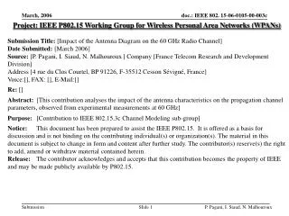
Project: IEEE P802.15 Working Group for Wireless Personal Area Networks (WPANs) Submission Title: [Impact of the Antenna Diagram on the 60 GHz Radio Channel ] Date Submitted: [March 2006]

E N D
Project: IEEE P802.15 Working Group for Wireless Personal Area Networks (WPANs) Submission Title: [Impact of the Antenna Diagram on the 60 GHz Radio Channel] Date Submitted: [March 2006] Source: [P. Pagani, I. Siaud, N. Malhouroux] Company [France Telecom Research and Development Division] Address [4 rue du Clos Courtel, BP 91226, F-35512 Cesson Sévigné, France] Voice:[], FAX: [], E-Mail:[] Re: [] Abstract: [This contribution analyses the impact of the antenna characteristics on the propagation channel parameters, observed from experimental measurements at 60 GHz] Purpose: [Contribution to IEEE 802.15.3c Channel Modeling sub-group] Notice: This document has been prepared to assist the IEEE P802.15. It is offered as a basis for discussion and is not binding on the contributing individual(s) or organization(s). The material in this document is subject to change in form and content after further study. The contributor(s) reserve(s) the right to add, amend or withdraw material contained herein. Release: The contributor acknowledges and accepts that this contribution becomes the property of IEEE and may be made publicly available by P802.15. P. Pagani, I. Siaud, N. Malhouroux
Impact of the Antenna Diagramon the 60 GHz Radio Channel P. Pagani, I. Siaud, N. Malhouroux Presented by: Wei Li Contact: wei3.li@francetelecom.com P. Pagani, I. Siaud, N. Malhouroux
Outline • Motivation • Propagation experiments • Antenna diagram vs. channel parameters • Antenna diagram vs. spatial variations • Effect of human motion on the radio link • Conclusion P. Pagani, I. Siaud, N. Malhouroux
Motivation • IEEE 802.15.3c Task Group currently studying possible PHY solutions for High Data Rate WPANs operating at 60 GHz • Channel modeling sub-group designing a propagation model for system simulations and optimization • Large beamwidth antennas and directive antennas are available for the mm wave frequency range • Which type of antennas are the most suited for the targeted applications? • Related research work has been performed within the European Commission FP6 integrated project MAGNET P. Pagani, I. Siaud, N. Malhouroux
The IST MAGNET project Personal Network concept Flexible PHY and MAC layer for WPANs Adaptive networks connected to WLANs, UMTS Leadership of the cluster UWB-MC Propagation studies : The UWB versus WB propagation modelling (CEPD, MASCARAA, 3GPP2 Publications : Magnet workshops WWRF, ECPS, SEE P. Pagani, I. Siaud, N. Malhouroux
France Telecom propagation expertise • Channel measurement laboratory • Frequency domain and time domain wideband channel sounders • Large number of measurement campaigns for different frequencies (900/1800 MHz, 2 GHz, ISM and UNII bands, UWB, 60 GHz) in different environment (indoor, urban, rural, …) and different configurations (SISO, MIMO, …) • Simulation tools for propagation analysis • Propagation model based on ray-tracing and Uniform Theory of Diffraction • Software tool providing WSSUS selectivity parameters • Propagation models • Narrowband: GSM, DCS • Wideband: UMTS, WiFi, millimeter waves • Ultra Wideband : {3.1-10.6} GHz, Millimeter waves • Link level models based on original tapped delay line models derived from measurements • Deterministic models based on the CEPD model (IST MAGNET) • Attenuation models including antenna diagram impact • Stochastic S-V type models derived from experimental measurements P. Pagani, I. Siaud, N. Malhouroux
Propagation experimentMeasurement environment • Residential environment: 100 m² apartment, LOS and NLOS situations • Tx: wide beam antenna • Rx: wide beam and directive antennas P. Pagani, I. Siaud, N. Malhouroux
Propagation experimentChannel sounding equipment • Vector Network Analyzer measurements with 1024 bandwidth around 60 GHz • Local measurements along a linear rail with 0.3-0.4 λ spacing • 3 types of vertically polarized horn antennas: 2 wide beam antennas (60° and 72° beamwidth) and 1 directive antenna (10° beamwidth) P. Pagani, I. Siaud, N. Malhouroux
26 0 8 Relative power (dB) Relative power (dB) Relative power (dB) 5.7 20.9 -5 3.4 15.8 1.1 10.7 -10 5.6 -1.2 -3.5 Azimuth (°) 0.5 -15 -5.8 -4.6 -20 -8.1 -9.7 Azimuth (°) -10.4 -14.8 -25 -12.7 -19.9 Azimuth (°) -15 -25 -30 -80 -64 -48 -32 -16 0 16 32 48 64 80 -40 -20 0 20 40 -120 -100 -80 -60 -40 -20 0 20 40 60 80 100 120 Propagation experimentAntenna diagrams Tx Rx Rx • Wide beam antenna • 72° beamwidth • 8 dBi gain • Wide beam antenna • 60° beamwidth • 13 dBi gain • Directive antenna • 10° beamwidth • 24.6 dBi gain P. Pagani, I. Siaud, N. Malhouroux
Similar attenuation ~15 dB Antenna diagram vs. channel parametersPath loss • NLOS : similar attenuation for wide beam and directive antennas • LOS : the use of a directive antenna reduces the path loss by ~15 dB Note that the Tx antenna pointed towards the Rx antenna during the experiment P. Pagani, I. Siaud, N. Malhouroux
Pos. 2 Pos. 2 Antenna diagram vs. channel parametersEffect of antenna misalignment Pos. 1 Directive (10°) Rx antenna • Antenna misalignment as small as +/- 5° leads to > 20 dB attenuation • Practical systems may not benefit from the gain from directive antennas Pos. 1 Wide beam (70°) Tx antenna P. Pagani, I. Siaud, N. Malhouroux
Antenna diagram vs. channel parametersPath loss models [1][3] Wide beam antenna Directive antenna • No NLOS path-loss distance dependency in the case of a Rx-directive antenna due to squint antenna effects P. Pagani, I. Siaud, N. Malhouroux
Antenna diagram vs. channel parametersDelay spread στ and delay window W90% Median values over all measurements • In both LOS and NLOS configuration, decrease of the delay spread and delay window when using directive antennas • With directive antennas, less multipath echoes are reaching the receiver P. Pagani, I. Siaud, N. Malhouroux
Antenna diagram vs. channel parametersExamples of Power Delay Profiles (LOS case) Rx Rx Rx 15° Tx Tx Tx • Wide beam antenna • στ = 2.96 ns • D(Tx-Rx)2 m. • Typical • Aligned directive ant. • στ = 0.62 ns • D(Tx-Rx) 4m • Typical • Misaligned directive antenna (15° offset) • στ = 2.67 ns • D(Tx-Rx) 1 m Similar Delay Spread for wide beam antenna and directive antenna with 15° offset and a reduced distance range D(Tx-Rx). Note: -40 dB threshold used in στ computation. P. Pagani, I. Siaud, N. Malhouroux
Typical and Atypical scenarios • Selection procedure of specific measurements to be fed to the CEPD model[2][3] • Relevant filter-based coefficients to simulate the channel at link level side. • Typical case : wideband selectivity parameters correspond to the average behaviour of the channel • Atypical Case : wideband selectivity parameters correspond to statistically extreme cases with CDF=0.8 P. Pagani, I. Siaud, N. Malhouroux
Rx Tx Antenna diagram vs. channel parametersTypical and atypical Power Delay Profiles (NLOS cases) Tx Rx • Wide beam antenna • στ = 6.92 ns • D(Tx-Rx) 8m • Typical case • Directive antenna • στ = 8.6 ns • D(Tx-Rx)6 m • Typical case • Directive antenna • στ = 13.6 ns • D(Tx-Rx) 12m • Atypical case Higher Delay Spread in case of directive beam antennas P. Pagani, I. Siaud, N. Malhouroux
Antenna diagram vs. spatial variations UWB power time variations LOS • Wide beam antenna • Multipath • Typical • Wide beam antenna • Multipath • Atypical • Directive antenna • Restricted Multipath • Typical • Directive antenna • Restricted Multipath • Atypical with a squint antenna effect Squint antenna involves power variations in the time domain combined with a dynamic range reduction P. Pagani, I. Siaud, N. Malhouroux
Antenna diagram vs. spatial variations UWB power time variations NLOS • Wide beam antenna • Multipath • Typical • Wide beam antenna • High Multipath combination • Atypical • Directive antenna • Multipath • Typical • Directive antenna • High Multipath combination • Atypical Squint antenna involves power variations in the time domain. High multipath combination may reduce squint antenna effects P. Pagani, I. Siaud, N. Malhouroux
Antenna diagram vs. spatial variationsDoppler spectrum [2] LOS situations • Wide beam antenna • Typical • Wide beam antenna • Atypical • Directive antenna • Typical • Directive antenna • Atypical • Wide beam antenna : Distinct doppler spread clusters in atypical situations • Directive antenna : Doppler spreading in the main peak in atypical situations • Antenna diagram removes Doppler clusters outside the main peak P. Pagani, I. Siaud, N. Malhouroux
Antenna diagram vs. spatial variationsDoppler spectrum [2] NLOS situations • Wide beam antenna • Typical • Wide beam antenna • Atypical • Directive antenna • Typical • Directive antenna • Atypical • Wide beam antenna : High doppler spread in typical/atypical situations • Directive antenna : Doppler spreading in the main peak in typical situations P. Pagani, I. Siaud, N. Malhouroux
7,83m R1/R2 T 478 4,78m People Motion V=0.6m/s Effect of human motion on 60 GHz radio link • Description of the experimentation : • Transmitter : omni –directionnal antenna • Receiver 1 : • wide-beam antenna (60 °) • Receiver 2 : • directive antenna (10°) P. Pagani, I. Siaud, N. Malhouroux
Effect of human motion on 60 GHz radio link Human shadowing→radio cut-off • Influence of the antenna aperture 10° • Directive antenna : • abrupt radio cut-off • Wide-beamantenna : • Small variations before radio cut-off • → possiblity of anticipating the radio cut-off 60° P. Pagani, I. Siaud, N. Malhouroux
Antenna diagram vs. Channel parametersResidential scenarios and associated WSSUS selectivity parameters [2] P. Pagani, I. Siaud, N. Malhouroux
Conclusion • A 60 GHz propagation experiment was conducted in the residential environment using wide beam (60°) and directive (10°) Rx antennas • The impact of the antenna directivity on the channel parameters was assessed • Directive antennas • Reduce the propagation loss: only if correctly aligned • Decrease the channel selectivity: by filtering out part of the (possibly significative) signal echoes • Limit dynamic range of CIRs when a squint antenna occurs • Limit energy capture when a squint antenna occurs over time-variant channels • May compensate squint antenna effects only on NLOS atypical cases • Wide beam antennas • Provide robustness against power fluctuations • Benefit from both multipath diversity and combination • Reduce deep fading amplitudes thanks to multipath combination • Recommandation: wide beam antennas are more appropriate than directive antennas for energy capture, multipath diversity and combination gains P. Pagani, I. Siaud, N. Malhouroux
References [1]: P. Pagani, N. Malhouroux, I. Siaud, "Characterization and modeling of the 60 GHz indoor channel in the office and residential environments", doc.: IEEE 802. 15-06-0041-00-003c, 12 january 2006. [2]: I. Siaud, "Combined Channel Coding and receiver antenna Pattern Influence on COFDM performance : Evaluation in a residential Indoor multipath environment at 60 GHz", International OFDM Workshop, September 10-11 th 2002, InOFW'2002, Hamburg [3]: I. Siaud, N. Malhouroux, V. Guillet, "Flexible Ultra-WideBand versus Wideband PHY layer Design and Performance for WPANs at 60 GHz (IST MAGNET project) ", European Conference Propagation and Systems, ECPS'05, 15-18 March 2005 . P. Pagani, I. Siaud, N. Malhouroux
Backup slides P. Pagani, I. Siaud, N. Malhouroux
Wideband characterizationAnalyzed parameters • For each measurement location, the Average Power Delay Profile P(τ) is computed from a number N of locally measured Channel Impulse Responses hn(τ) • Wideband characteristics of the 60 GHz channel assessed by statistical analysis of selected selectivity parameters: • Delay spread στ • Coherence bandwidth at n% Bc,n% • Delay window at q% Wq% • Delay interval at p dB Ip dB P. Pagani, I. Siaud, N. Malhouroux