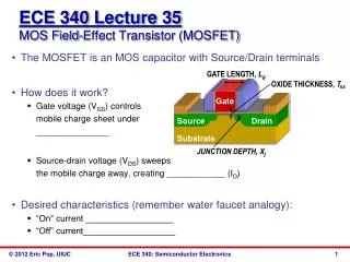
– MOSFET
POWER TRANSISTOR. – MOSFET. Example of power MOSFET parameters;. POWER TRANSISTOR. – MOSFET. The superior characteristics of MOSFETs are; Faster switching time; No second breakdown; Stable gain and response time over a wide temperature range (Figure on the next slide). POWER TRANSISTOR.


– MOSFET
E N D
Presentation Transcript
POWER TRANSISTOR – MOSFET Example of power MOSFET parameters;
POWER TRANSISTOR – MOSFET • The superior characteristics of MOSFETs are; • Faster switching time; • No second breakdown; • Stable gain and response time over a wide temperature range (Figure on the next slide).
POWER TRANSISTOR – MOSFET Transconductance versus drain current curves for various values of temperature – less than the variation in BJT current gain.
POWER TRANSISTOR – MOSFET Transfer characteristics curves for various values of temperature.
POWER TRANSISTOR – MOSFET Structure
POWER TRANSISTOR – MOSFET Structure DMOS process can be used to produce a large number of hexagonal cells on a single chip.
POWER TRANSISTOR – MOSFET Structure These hexagonal cells can be paralleled to form large-area devices without the need of emitter ballast resistance. A single power MOSFET may contain as many as 25,000 parallel cells.
POWER TRANSISTOR – MOSFET The “ON” resistive path between drain and source (rds(on)) is an important parameter in power capability of MOSFET
POWER TRANSISTOR – Comparison BJT Requires complex input circuitry because of high input current (current-controlled device) More sensitive to temperature variation – thermal runaway and problem of second breakdown. MOSFET Simple input circuitry because of low input current (voltage-controlled device). More immune to thermal runaway and second breakdown.
POWER TRANSISTOR – Heat sinks • The power dissipated in a transistor can cause an internal temperature rise above ambient temperature. • This heat, if not properly removed, may cause internal temperature above a safe limit and can cause permanent damage to transistor. • Heat may be removed through proper packaging:
POWER TRANSISTOR – Heat sinks • Additionally, heat sinks can be used to remove the heat developed in the transistor:
POWER TRANSISTOR Heat sinks (Extra) Temperature of transistor junction Ambient temperature Electrical equivalent circuit of thermal-conduction process Temperature difference Voltage difference Thermal resistance between the junction and ambient Electrical resistance Thermal power through the element Electric current.
POWER TRANSISTOR Heat sinks (Extra) • Manufacturers’ data sheet for power devices generally give: • maximum operating junction (device) temperature, TJmax; • thermal resistance from the junction to the case, JC; The temperature conduction process may be represented as follows:
POWER TRANSISTOR Heat sinks (Extra) The following equation can be used to describe the temperature conduction process: If the heat sink is not used, then;
POWER TRANSISTOR Heat sinks (Extra) EXAMPLE 8.3 A MOSFET has the following parameters; Determine the maximum power dissipation in the transistor and determine the temperature of the transistor case and heat sink.
POWER TRANSISTOR Heat sinks (Extra) EXAMPLE 8.3 – Solution Maximum power (without heat sink) Maximum power (with heat sink)
POWER TRANSISTOR Heat sinks (Extra) EXAMPLE 8.3 – Solution (cont’d) Heat sink temperature
POWER TRANSISTOR Heat sinks (Extra) EXAMPLE 8.3 – Solution (cont’d) Case temperature Note: The use of heat sink allows more power to be dissipated in the device.
POWER TRANSISTOR Heat sinks (Extra) • Power derating curve • Manufacturer usually specifies: • the maximum temperature TJmax; • the maximum power dissipation PDmax, at a particular ambient temperature TA0 (usually 25C); and • the thermal resistance JA. In addition, a graph – power derating curve is provided.
POWER TRANSISTOR Heat sinks (Extra) Power derating curve For operation below TA0, the device can safely dissipate the rated value of PD0 watts. If the device is to be operated at higher ambient temperature, the maximum allowable power dissipation must be derated according to the straight line.