Simple Machines
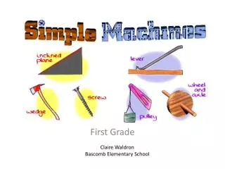
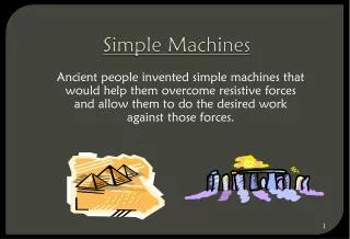
Simple Machines. Ancient people invented simple machines that would help them overcome resistive forces and allow them to do the desired work against those forces. Simple Machines. The Lever. A lever is a rigid bar or board that rotates around a fixed point called the fulcrum .

Simple Machines
E N D
Presentation Transcript
Simple Machines Ancient people invented simple machines that would help them overcome resistive forces and allow them to do the desired work against those forces.
The Lever A lever is a rigid bar or board that rotates around a fixed point called the fulcrum. • The bar may be either straight or curved. • In use, a lever has both an effort (or applied) force and a load (resistant force).
Levers can be used to exert a large force over a small distance at one end by exerting only a small force over a greater distance at the other.
The 3 Classes of Levers The class of a lever is determined by the location of the effort force and the loadrelative to the fulcrum.
The 3 Classes of Levers “R” is the resistance force which is the load. “E” is the human effort force applied. The fulcrum is the fixed point support on which a lever pivots
First Class Lever In a first-class lever the fulcrum is located at some point between the effort and resistance (load) forces. • Common examples of first-class levers include crowbars, scissors, pliers, and seesaws. • A first-class lever always changes the direction of force (I.e. a downward effort force on the lever results in an upward movement of the resistance force).
Fulcrum is between EF (effort) and RF (load)Effort moves farther than Resistance.Multiplies EF and changes its direction
Second Class Lever With a second-class lever, the load is located between the fulcrum and the effort force. Common examples of second-class levers include nut crackers, wheel barrows, doors, and bottle openers. A second-class lever does not change the direction of force. When the fulcrum is located closer to the load than to the effort force, an increase in output force (mechanical advantage) results.
RF (load) is between fulcrum and EF Effort moves farther than Resistance.Multiplies EF, but does not change its direction
Third Class Lever • With a third-class lever, the effort force is applied between the fulcrum and the resistance force. • Examples of third-class levers include tweezers, hammers, and shovels. • A third-class lever does not change the direction of force; third-class levers always increase distance and a corresponding decrease in force.
EF is between fulcrum and RF (load) Does not multiply force Resistance moves farther than Effort.Multiplies the distance the effort force travels
Lever Mechanical Advantage MA = length of effort arm ÷ length of resistance arm If the effort arm distance (from effort to fulcrum) is greater than the resistance arm, then the effort required will be less than the load being moved. This is known as a 'positive mechanical advantage'.
Wheel and Axle • The wheel and axle is a simple machine consisting of a large wheel rigidly secured to a smaller wheel or shaft, called an axle. • When either the wheel or axle turns, the other part also turns. One full revolution of either part causes one full revolution of the other part.
Pulley A pulley can be • Fixed • Movable A pulley consists of a grooved wheel that turns freely in a frame called a block.
Fixed Pulley A pulley is said to be a fixed pulley if it does not rise or fall with the load being moved (only spins). A fixed pulley changes the direction of a force.
Moveable Pulley A moveable pulley rises and falls with the load that is being moved. A single moveable pulley does not change the direction of a force. Movable pulleys increase force and distance over which the input force must be exerted.
Block and Tackle(Compound Pulley) Combines fixed and movable pulley – sometimes more than one of each.
A Pulley’s Mechanical Advantage The Mechanical Advantage of a pulley equals the number of rope segments that support the load. MA = 4 (Don’t count the rope you are pulling)
Inclined Plane An inclined plane is an even sloping surface. The inclined plane makes it easier to move a weight from a lower to higher elevation.
Inclined Plane • The mechanical advantage of an inclined plane is equal to the length of the slopedivided by the height of the inclined plane. • While the inclined plane produces a mechanical advantage, it does so by increasing the distance through which the force must move.
Although it takes less force for car A to get to the top of the ramp, all the cars do the same amount of work. A B C
Inclined Plane • A wagon trail on a steep hill will often traverse back and forth to reduce the slope experienced by a team pulling a heavily loaded wagon. • This same technique is used today in modern freeways which travel winding paths through steep mountain passes.
Wedge • The wedge is a modification of the inclined plane. Wedges are used as either separating or holding devices. • A wedge can either be composed of one or two inclined planes. A double wedge can be thought of as two inclined planes joined together with their sloping surfaces outward.
The Screw • The screw is also a modified version of the inclined plane. • While this may be somewhat difficult to visualize, it may help to think of the threads of the screw as a type of circular ramp (or inclined plane).
A Screw’s MA ~ The longer and thinner the screw is the greater the MA…Similarly, the longer the spiral on the screw and closer together the threads are, the greater the MA.