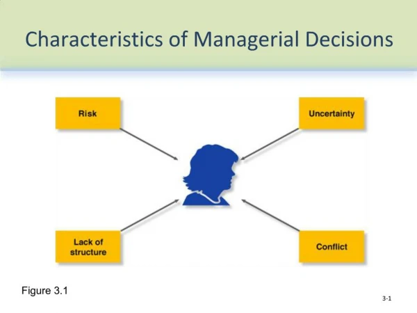
Programmed I/O (Polling)
68000. CPU. Is the data ready?. System Bus. no. 68230. Memory. IOC. yes. read data. device. Terminal Mouse Keyboard/Switches etc. store data. A busy-wait loop is used in this I/O method Not an efficient way to use the CPU unless the

Programmed I/O (Polling)
E N D
Presentation Transcript
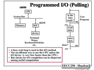
68000 CPU Is the data ready? System Bus no 68230 Memory IOC yes read data device Terminal Mouse Keyboard/Switches etc. store data • A busy-wait loop is used in this I/O method • Not an efficient way to use the CPU unless the • I/O device is very fast (faster than the CPU). • But checks for I/O completion can be dispersed • among useful computation done? no yes Programmed I/O (Polling) User Program
68000 Interrupt Lines 7 add sub and or nop CPU User Program (normal execution) (1) I/O interrupt System Bus (2) save PC, SR 68230 Memory IOC (3) Go to interrupt service routine (ISR) address device lea move ... rte Terminal Mouse Keyboard/Switches etc. (4) Restore PC, SR Return to user program memory • User program normal execution only halted during • actual data transfer • More efficient than polling I/O Interrupt-Driven Data Transfer
Interrupts & Exceptions • Conditions interrupting ordinary program execution are called exceptions when caused by software sources internal to the CPU. • Interrupts are exceptions which are caused by hardware sources external to the CPU. • An interrupt or exception generally requires special handling by the CPU in terms of executing an Interrupt Service Routine (ISR). • Example: An I/O device informs the CPU that data is ready and requests special processing by setting an Interrupt Request line (IRQ) to True. • 68000 has 7 such IRQ lines: (IRQ1-IRQ7). • If two hardware interrupts occur simultaneously the IRQ with a higher priority (higher IRQ number) gets serviced. • An interrupt with a higher IRQ can interrupt the ISR of an interrupt with a lower IRQ.
Vectors 64-255 are user interrupt vectors Vectored Interrupts • When the 68000 senses that an Interrupt Request is pending it stops the normal program execution and must identify the type of interrupt or exception to execute the correct handling routine. • The 68000 must be in supervisor mode as set in SR (S bit = 1) to handle interrupt routines. • The 68000 allows 255 such routines and stores their location (called a vector) addresses in the first 1K of 68000 program memory. • This area is called the exception vector table: • vector #1 - SPECIAL - for system start-up • vector #2 ….. • vector #255 • Address of exception vector = 4 x exception vector number
68000 (PIT, etc.) Vectored Interrupts • The interrupt vector is provided to the CPU on the data bus by the interrupting I/O device from an interrupt vector register: • When the 68000 accepts the interrupt, it acknowledges this to the device using line IACK and it looks for the interrupt (or exception) vector on the data bus.
Status Register (SR) & Interrupts • I2 I1 I0 : Interrupt level (interrupt mask bits, value range = 0 to 7) • The 68000 only accepts interrupts with a higher • level than that set by the interrupt mask bits • An interrupt with level 7 cannot be masked and must • be accepted by the 68000. • When an interrupt is accepted I2 I1 I0 • (Interrupt mask) is set to the current interrupt level.
Interrupt Handling Steps When an interrupt is requested by I/O and accepted by the CPU… 1.CPU finishes executing the current instruction 2. Acknowledge the acceptance of the interrupt to the I/O device. 3. Device provides interrupt vector after the acknowledgement. 4. Determine the start address of ISR (which interrupt vector). • Usually from the exception vector table in memory. 5. Push PC and Status Register, SR on stack. 6. Initialize the status register (for the exception routine) • Usually, set S = 1, T = 0, update interrupt level in SR for external exceptions to the current accepted interrupt level 7. Load ISR start address into PC 8. ISR proceeds to execute like a normal subroutine except it must end with the instruction: RTE ReTurn from Exception (similar to RTS, pops PC and SR from system stack)
Format of 68230 Port General Control Register, PGCR PGCR7 PGCR6 PGCR5 PGCR4 PGCR3 PGCR2 PGCR1 PGCR0 Port Mode Control 00 Mode 0 01 Mode 1 10 Mode 2 11 Mode 3 H34 Enable H12 Enable H4 sense H3 sense H2 sense H1 sense 0 Disable 1 Enable 0 Active low 1 Active high • Example: • PGCR = %00010000 • Means: • Mode 0, Unidirectional 8-bit, separate PA & PB • H34 handshaking disabled • H12 handshaking enabled • H4-H4 active low
PSR7 PSR6 PSR5 PSR4 PSR3 PSR2 PSR1 PSR0 H4 Level H3 Level H2 Level H1 Level H4S H3S H2S H1S Set by line depending on mode Follow level of line 68230 Port Status Register, PSR • Reflects activity of the handshake lines PSR0-PSR3 must be cleared by the program by writing a 1 onto them
Format of Port A Control Register in Mode 0 PACR PACR7 PACR6 PACR5 PACR4 PACR3 PACR2 PACR1 PACR0 Submode: 00 submode 0 01 submode 1 10 submode 1x H2 Control 0xx Edge-sensitive input 100 output- negated 101 output - asserted 110 output - interlocked handshake 111 Output - pulsed handshake H2 Interrupt 0 Disabled 1 Enabled H1 Control 0X H1 interrupt disabled 10 H1 interrupt enabled XX • Example: PACR = %00000010 • PADDR = %00000000 • Means: Port A is used as an input port • Submode 0 (Double Buffered input) • H2 Edge-sensitive • H2 interrupt disabled • H1 interrupt enabled
PSRR7 PSRR6 PSRR5 PSRR4 PSRR3 PSRR2 PSRR1 PSRR0 X DMA Control Interrupt Control Port Priority Control 68230 Port Service Request Register PSRR (PIT + $02) • Determines PIT interrupt/DMA settings Port Interrupt Priority Order of Priority PSRR2 PSSR1 PSSR0 Highest Lowest 0 0 0 H1S H2S H3S H4S 0 0 1 H2S H1S H3S H4S 0 1 0 H1S H2S H4S H3S 0 1 1 H2S H1S H4S H3S 1 0 0 H3S H4S H1S H2S 1 0 1 H3S H4S H2S H1S 1 1 0 H4S H3S H1S H2S 1 1 1 H4S H3S H2S H1S PSRR4 PSRR3 0 0 No interrupt support 0 1 Autovectored interrupts 1 0 1 1 Vectored interrupts supported
Interrupt Vector Number Interrupt Source PIVR1 PIVR0 H1 0 0 H2 0 1 H3 1 0 H4 1 1 Format of 68230 Port Interrupt Vector Register PIVR (PIT+$0A) PIVR7 PIVR6 PIVR5 PIVR4 PIVR3 PIVR2 PIVR1 PIVR0 Selected Automatically User Defined Value
Addresses of Port Related Registers Addresses of Timer Related Registers PIT EQU $0FF000 Base Address of PI/T PGCR EQU PIT Port General Control Register PSRR EQU PIT+2 Port service request register PADDR EQU PIT+4 Data direction register A PBDDR EQU PIT+6 Data direction register B PCDDR EQU PIT+$08 Data direction register C PIVR EQU PIT+$0A Port Interrupt Vector register PACR EQU PIT+$0C Port A control register PBCR EQU PIT+$0E Port B control register PADR EQU PIT+$10 Port A data register PBDR EQU PIT+$12 Port B data register PCDR EQU PIT+$18 Port C data register PSR EQU PIT+$1A Port status register TCR EQU PIT+$20 Timer control register TIVR EQU PIT+$22 Timer interrupt vector register CPR EQU PIT+$24 Dummy address of preload register CPRH EQU PIT+$26 Timer preload register high CPRM EQU PIT+$28 Timer preload register middle CPRL EQU PIT+$2A Timer preload register low CNTR EQU PIT+$2C Dummy address of timer register CNTRH EQU PIT+$2E Timer register high CNTRM EQU PIT+$30 Timer register middle CNTRL EQU PIT+$32 Timer register low TSR EQU PIT+$34 Timer status register 68230 Registers Address Equates
Interrupt-Driven PIT Input Example • Input one byte from port A and buffers it in memory, whenever an interrupt is received on line H1 * Main Program H1_VEC EQU 68 PIT Exception vector number H1_V_A EQU H1_VEC*4 ISR Exception vector table address PGCRM EQU %00010000 Mode 0, submode 00 PACRM EQU %00000010 PGCR value to enable H1 interrupt ORG $1000 MAIN MOVEA.L #$07FFE,A7 Initialize SP LEA H1_ISR,A0 Load A0 with address of PIT Routine MOVE.L A0,H1_V_A Put ISR address in vector table MOVE.B #H1_VEC,PIVR Initialize PIVR with interrupt vector MOVE.B #PGCRM,PGCR Initialize PGCR MOVE.B #PACRM,PACR Initialize port A MOVE.B #$00, PADDR Set Port A as input MOVE.B #%00011000,PSRR Enable vectored interrupts in PSRR LEA BUFFER,A1 Load DATA address in A1 ANDI #$0F0FF,SR Enable interrupts in SR LOOP NOP Fake loop just for example BRA LOOP main program doing other tasks here
Interrupt-Driven PIT Input Example **** PIT Interrupt Service Routine H1_ISR * H1_ISR ORI #$0700,SR Disable interrupts MOVE.B PADR,D1 Get a byte from port A MOVE.B D1,(A1)+ Store byte in memory buffer ANDI #$0F0FF,SR Enable interrupts RTE Return from exception STOP #$2700 ORG $2000 BUFFER DS.B 1000 reserve 1000 bytes for buffer END
Timer Control Register (TCR) Value To Enable Periodic Timer Interrupt TCR7 TCR6 TCR5 TCR4 TCR3 TCR2 TCR1 TCR0 Timer Enable Tout/TIACK* Control Zero-detect Control None Clock Control 1 0 1 0 0 0 0 1 After ZD, counter restarts from initial preloaded value PC3/Tout used as timer interrupt request line PC7/TIACK* used to acknowledge timer interrupts PC2/Tin not used counter clock CLK/32 Enable timer
Periodic Timer Interrupts Example • The subroutine T_SET preloads the timer with an initial value, and enables timer interrupt. • Once the timer is enabled by calling T_SET, an interrupt is generated periodically to perform the tasks in the timer interrupt service routine, T_ISR. * * Timer setup subroutine: T_VEC EQU 70 Timer Exception vector number T_V_A EQU T_VEC*4 ISR Exception vector table address ORG $1000 T_SET LEA T_ISR,A0 Load A0 with address of Timer ISR MOVE.L A0,T_V_A Put Timer ISR address in vector table MOVE.B #T_VEC,TIVR Initialize TIVR with interrupt vector MOVE.L #$00FFFFFF,D0 Set maximum count MOVE.L D0,CPR preload count value in CPR MOVE.B #%10100001 set up TCR, enable timer RTS * Timer interrupt service routine. T_ISR MOVE.B #1,TSR Clear ZDS bit in TSR * . . . . . . * . . . Do tasks needed in ISR RTE