Download
1 / 31
310 likes | 413 Views
Restructuring the Physics 234 Course to Include Nanoscale Investigations. Stephanie Barker and Kurt Vandervoort Funding for this project was provided by the National Science Foundation Nanotechnology Undergraduate Education Program Award #0406533. Purpose of the Project.

E N D
Restructuring thePhysics 234 Course to Include Nanoscale Investigations Stephanie Barker and Kurt Vandervoort Funding for this project was provided by the National Science Foundation Nanotechnology Undergraduate Education Program Award #0406533.
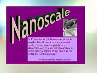
Purpose of the Project • To develop modules to introduce atomic force microscope (AFM) applications into the Physics 234 course. • To investigate surfaces at the microscopic level to reveal properties which account for macroscopic-scale phenomena in light. • To introduce and familiarize students with research-grade equipment at an introductory level as important career preparation. • To explore interesting engineering applications of nanotechnology.
Existing Course Lab Structure Experiments: Data Analysis A.C. Circuits Microwave Optics Geometric Optics Physical Optics Spectroscopy Speed of Light Michelson Interferometer Proposed Revisions to Lab Structure Experiements: Data Analysis A.C. Circuits Geometric Optics* Physical Optics* Spectroscopy* Microwave Optics* Speed of Light Michelson Interferometer Appendix A** Proposed revisions reflect the need to present physics concepts in an order that introduce AFM applications in the proper context.* Modifed Lab Modules** An Appendix was added as a basic reference for the standard operation of the AFM
Geometric Optics Module • Existing Objectives • To observe the interaction of light with prisms, mirrors and lenses • To measure refraction, reflection, critical and Brewster’s angles • To verify the laws of reflection/refraction and the lens maker’s equation • Additional AFM Module Objectives • To visually examine rough and smooth gold plated slides to verify specular or diffuse reflection • To observe the microscopic surface topography of these slides • Learning Enhancements • Students will be able to directly confirm criteria that define the limit for geometric optics by distinguishing the microscopic origin of specular and diffuse reflection.
Gold Plated Slides Exhibiting Specular and Diffuse Reflection
Cross-Section of Specularly Reflective surface • Surface feature widths and lengths ~ 0.5 μm or 500 nm • Surface feature heights ~ 10 nm • Surface feature heights are significantly less than the wavelengths of visible light (400-700 nm)
Cross-Section of DiffuseReflective Surface • Surface feature widths and lengths ~ 20μm or 20000 nm • Surface feature heights ~ 2000 nm • Surface feature dimensions much larger than the wavelengths of visible light (400-700 nm)
Physical Optics Module • Existing Objectives • To observe the basis for the wave theory of light • To study the diffraction and interference of light • To calculate the wavelength of light • Additional AFM Module Objectives • To visually examine the surface of an iridescent butterfly wing • To observe the microscopic surface topography of the wing • To observe the microscopic surface topography of a compact disc • Learning Enhancements • Students will be able to see direct applications of physical optics in both natural and industrial materials.
Effects of Thin-Layer Interference • The bright, shifting colors of a butterfly wing are due to interference which occurs in a series of thin layers on the surface of the wing. • These structures can cause constructive interference for certain wavelengths of visible light, so that some colors seem more brilliant than usual. • The colors may change as you (or the butterfly) change position, and the interference becomes visible at different angles of view.
Interference in Thin Layers • The film layer has thickness t and index of refraction n > nair • The wavelength λn of light in the film layer is λn = λ/n • Ray B travels a distance 2t further than Ray A before the waves recombine in the air above the film and interfere • Ray A has an additional 180 degree phase shift following reflection
Condition for Constructive Interference in Thin Films • If 2t = λn /2, then rays A and B recombine in phase, and constructive interference occurs, so: 4nt = λ where n is the index of refraction of the film, m is the order of interference, and λ is the wavelength of light in air.
CD Exhibiting the Effects of a Reflective Diffraction Grating
Size of surface features are on the order of the wavelength of visible light. Height of surface bumps is between 120 and 130 nm. Cross-section of Compact Disc
Physics of a Compact Disc • The bumps that were imaged by the AFM are variations in a thin polycarbonate layer. As the CD is “read” a laser is focused onto the region of these bumps. • When the laser spot encounters a bump, half of the area of the spot covers the bump, and half covers the flat area surrounding the bump. The waves that are reflected from these two different heights destructively interfere. • The condition for destructive interference depends on the wavelength of the laser light in the polycarbonate layer.
reflection from bump reflection from flat area Laser spot polycarbonate material Bump Top View Side View Using Destructive Interference to Read a Compact Disc
The condition for destructive interference between two waves is such that the total pathlength differs by a distance that is ½ the wavelength. • In this case, the laser light is emitted from the same location, and the bump is the only change in pathlength that the waves encounter. The waves that encounter the flat areas travel a distance further than those encountering the bumps. This extra distance is equal to twice the height of the bump (2h). • This difference in pathlength must be equal to ½ wavelength for destructive interference, so: 2h = ½ λ, orh = λ/4
Expected Height of Bumps in Polycarbonate Layer • λ0 ≡ wavelength of laser (in air) = 780 nm • λ ≡ wavelength in polycarbonate layer • n ≡ index of refraction for polycarbonate layer = 1.56 λ = λ0/n = 500 nm λ/4 = 125 nm • The cross-section of the CD scan does show surface feature heights that are near this value.
Spectroscopy Module • Existing Objectives • To observe the effects of a multiple-slit diffraction grating on the polychromatic light emitted from gas spectra tube • To understand how spectroscopy can be used to find the characteristic spectrum of a gas, and furthermore identify each element present. • Additional AFM Module Objectives • To view a microscopic image of the diffraction grating used and compare its actual features with any original assumptions about the construction of the grating • Learning Enhancements • Students will be able to closer observe the results of intricate machining involved in the application of nanoscale technology. • Students will be introduced to the microscopic topography of a “blazed” diffraction grating.
Image of a Multiple-SlitDiffraction Grating • The “grating” is not actually a series of slits, but a series of angled grooves. Th size of these features is on the order of the wavelength of light.
Microwave Optics Module • Existing Objectives • To gain some familiarity with microwave techniques and equipment. • (Optional) To show that microwaves, like light, are transversely polarized electromagnetic waves. • Additional AFM Module Objectives • To determine the blaze angle for a standard diffraction grating by analyzing the cross-section of an AFM image. • To observe the double-slit interference pattern for microwaves. • To observe the effects of a macroscopic blazed diffraction grating on the diffraction envelope. • Learning Enhancements • Students will experience the advantages of a blazed diffraction on the macroscopic scale.
Blazed Diffraction Grating Cross-section • The height and width of the grooves can be used to determine the shallower angle, which is the blaze angle. • Average groove spacing as measured by AFM is 1600 nm. • This result is within 5% of the nominal spacing, considering 600 lines/mm. • The blaze angle is measured to be 23o, which is within 10 % of the manufacturer’s specification.
groove surface sin-1(nsinqB) qB m = 2 back of grating m = 1 m = 0 m = -1 m = -2 qB Blazed Diffraction Gratings • By blazing the grating the diffraction envelope can be shifted so that the maximum intensity occurs for higher-order maximum (m>1) of the interference pattern. Blaze condition: sin-1(n sin θB) – θB = θm
T Plates Grating q R - + Setup for the Microwave Experiment
Results for the Microwave Experiment(Slit width = 4 cm; Slit separation = 6 cm) White data points: No diffraction grating used Black data points: Macroscopic diffraction grating used • The intensity maximum of the diffraction envelope is shifted to the m = -1 position.
Overview of Appendix A:Basic OperationInstructions for the AFM • Includes background theory of atomic force microscopy • Gives a detailed explanation of the functions of the software used to perform a scan with the AFM, including an index of the icons. • Includes the step-by-step procedure for configuring the scanning parameters and operating the instrument • Explains several methods of analysis for an image, including the 3D Image, Histogram, and Dimensional Analysis functions.