Download
1 / 13
130 likes | 298 Views
WG3 (Cryomodule) summary & plan with recommendation to the CB. V.Parma, CERN TE-MSC P. DUTHIL, IN2P3-CNRS. Objectives. Warm or cold magnets? Technical spec. and interfaces for cavity helium vessel and tuner Coupler requirements and assembly constraints

E N D
WG3 (Cryomodule) summary & plan with recommendation to the CB V.Parma, CERN TE-MSC P. DUTHIL, IN2P3-CNRS 3rd SPL collaboration meeting, CERN 11-13 November 2009
Objectives Warm or cold magnets? Technical spec. and interfaces for cavity helium vessel and tuner Coupler requirements and assembly constraints Alignment requirements for cavities and quads Dimensions , T and P for cryomodule cryogenic lines (depending on cryogenic scheme adopted) Prepare ingredients for: The preparation of the technical specification for the prototype cryomodule And refining the objectives for the prototype cryomodule program
Machine layout issues & recommandation Key feature (outcome sectorisation workshop): availability of the machine High reliability/maintainability Possibility of changing a cryomodule with “short” intervention Full segmentation seems an interesting option But needs to be deepely analysed (technical/cost) Segmentation has important impact on cryomodule design: Cryogenics lines sizes and layout Technical service module Connection to CDL C/W transitions 1/2
Machine layout issues & recommandation Nominal temperature: For the time being: Tmax = 2K (31mbar) on each He bath (outside cavity surface) T optimisation seems necessary: decreasing the temperature: Q versus cryogenics cost 2/2
Magnets issues FD and FODO schemes seems equivalent; FD seems to be preferable for reduced layout length. For low β: possibility of changing the scheme (FD+3+FD+3) may result in more compact layout. To be further investigated. No impact for β=1 prototype cryomodule New Quad alignment spec.: ±0.2mm (1) Not impossible but tight (XFEL has± 0.3mm) Major advantage for having warm magnets Correction (to be included in the general mech. layout): 1 steerer for each quad; Diagnostic : Today 1 BPM per quadrupole doublet (mid length) Possibility of using BPM as diagnostics for matching (QPU), but position between doublet to be reviewed Need of additional diagnostic to be included ? 1/2
Magnets issues SPL quadripole, in general easy design (both warm and cold versions) Possibility of warm magnets would result in full segmentation with distribution line Present layout: 10 Tesla/m ; L ≤ 400mm ; Ø~400mm ; m~300kg; consistant with the present layout for segmented version; but: 1 steerer to be included in the design, the H- stripping has to be further inverstigated, could require reduced gradient i.e. longer magnets (=longer machine) BPM could be placed within the warm quad (outer diam. then slightly larger) Estimated total power consumption : 400kW Heat loads: ~10-2, 10-1 W @2K Pulsed working conditions (several Hz, could be up to 50 Hz): → no pb (but care concerning the coupling with the power supply); Permanent magnet version still would require trimming; Power converter architecture (individual or series) to be compared; Further comparison between power converters for cold or warm magnets 2/2
Coupler integration needs Outer conductor of coaxial power coupler in contact with LHe bath at the coupler/cavity interface; Heat intercept: 5-8K not optimal; other temperature range can be investigated: eg. 2K spilling, warm-up from ~5K up to 300K Position : vertical upward is the prefered option for wave guide connection in the tunnel & transportation Consequence for cryomodule design: bi-phase pipe needs to be sideways (has to be above cavity)
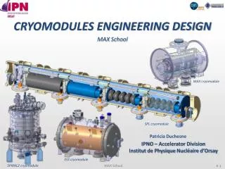
Cavity He vessel and tunner assembly LHe tank: Ti for the prototype Coupler port directly in the 2K LHe bath Heat loads: what are the static and dynamic loads? Presently adopted inter-cavity bellow zone is questioned in terms of leaking field and associated heat loads. It could be subjected to change Present cavity alignment spec. (not addressed in this workshop): ±0.5mm (1) Microphonics : tuner may handle it
(Dynamic & static) Heat loads Present budgets are based on bibliography. More specific values for SPL should be elaborated: dynamic losses should evaluated on (SPL type) representative set of cavities only Static losses: also depending on segmentation choice HP SPL: 10% cryogenic duty cycle doubles heat laods compared with formal version → double the installed cooling capacity needs → increases the cryogenic line diameter: x1,4 → requires investigation on the cavity surface heat exchange
Cryogenics issues Pressures specifications are proposed: Design pressure for cavity and low pressure circuit have to be defined (6 bar seem too high for cavities): Maximum allowable pressure (at RT and at cold) will be checked by CEA A cryogenic scheme has to be chosen and further investigated Number of pipes (inside the cryostat) Pipes diameters (at present only sizes for distribution lines presented) HP new version heat loads have a fundamental impact on pipes sizes (cryomodule design) and cryoplant Avoid flanges for interfaces into the cryogenic piping
Survey issues The alignment of the SPL is not reallychallenging (if SPL - SPS connectionavailable) Cryostat must be equipped with survey reference targets and a tilt reference (standard LHC equipment) Cryostat must be supported with a precise realignment system (e.g. LHC jacks system) Internalmetrologywillbe more challenging Alignmentmethodshouldbedecided(e.g. laser tracker): → position of the alignmentfiducialsw.r.t a reference axis (by measurement or adjustment of fiducials) For the cryostat prototype: need to verify the internal position of the components monitoring of the cavities and quads with respect to externalfiducials on the cryostat (sensor type and protocolshouldbechosen) Integratealignement metrologyin the design Use of WPM (Tesla system) shallbeinvestigated
Further work • Cryomodule prototype requires urgent (end of the year) decisions to be in timr for 2012: • Refining objectives of the prototype • Choice of layout segmentation • Choice of cryogenic “baseline” scheme • HL to be coped with (HP new version!) • Cooling scheme (also choice for coupler) • Final sizes, pressures, temperature Support from the Collaboration Board is needed to freeze the objective of the prototype 3rd SPL collaboration meeting, CERN 11-13 November 2009
Thank you for your attention!Special thanks to all speakers for their excellent work! 3rd SPL collaboration meeting, CERN 11-13 November 2009