Download
1 / 13
140 likes | 362 Views
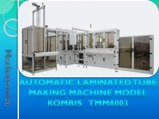
KOMBIS TMM8003 Installation Communication and Control. Communication and Control Block Diagram. Communication and Control.

E N D
Communication and Control • Microprogrammes control the KOMBIS TMM8003. For the reliable operation of its systems and devices there are several programs located in two controllers – the main controller and the motion controller. • The main controller (master) ensures machine control by: • Submitting commands to drive all the mechanisms in the machine and controlling their functions • Displaying information about the communication between operator and machine • Remembering statistics of the machine operation for a long period of time • Communicating through a LAN connection with a remote computer for inputting or outputting data. • The motion controller (slave) is a sub-executive computer (controller) that controls some of the motor actuation mechanisms in the machine. Its communication with the main controller is via LAN connection for slow processes (error messages and status of the controller) and via the input-output (I/O) signals for fast processes (command “Start process”- answer “Ready / Busy”).
Communication and Control • MAIN CONTROLLER Graphic Symbol The Main controller of KOMBIS TMM8003 is based on a ”Beckhoff CX1020” embedded PC. This is a modular control system designed for top-hat rail installation. The system is scalable, so that the required modules can be assembled and installed in the control cabinet or terminal box as required . The main controller is located on the top row in the main panel of the machine. It includes the following modules: Basic CPU - including a 64MB Compact Flash card and two Ethernet RJ45 interfaces DVI + 2xUSB Serial interface for RS232 Power supply unit for E-Bus Local E-Bus IO terminals Extension module for EtherCAT 3 2 4 1 5 6 Location
Communication and Control • MAIN CONTROLLER The basic configuration of the CX1020 [1] includes a 64MB Compact Flash card. The two Ethernet RJ45 interfaces are also part of the basic configuration. These interfaces are connected to an internal switch and offer a simple option for creating a line topology without the need for additional Ethernet switches. All other CX family components are connected to CX1020 via the PC104 interface that is available on both sides. These devices in the KOMBIS TMM8003 are: DVI + 2xUSB Module [2], 2xRS232 module [3] and Power supply unit for E-Bus terminals [4]. The local EtherCAT terminals [5] are connected to the power supply unit [4]. Through this unit the I/O data are stored directly in the main memory of the CPU (intermediate memory is not required). The EtherCAT terminal ends with an end terminal (“cap”) or extension module for EtherCAT [6]. The "Beckhoff" systems allow, using Extension modules for EtherCAT, to build "islands" of input-output terminals away of the main controller (EtherCAT Bus terminals) or connect other devices operating with EtherCAT interface to the main controller. Such input-output devices connected in the EtherCAT Bus of the main controller in the KOMBIS TMM8003 are:
Communication and Control • EtherCAT Communication Main Controller Located in the body maker under body welding mechanism Located in the cabinet of the unwinding mechanism Located in the capping station’s control and pneumatic cabinet Located in the capping station under the rotary table
Communication and Control • MOTION CONTROLLER Graphic Symbol The “Trajexia” motion controller in the KOMBIS TMM8003 is a dedicated motion system made by the ”OMRON” company. It is a stand-alone modular system for the control of up to 16 axis of servos, inverters and I/O modules connected to a robust and fast single network named MECHATROLINK-II. The motion controller is located in the middle of the motion control cabinet of the machine. It includes the following Trajexia family of modules: Power supply (CJ1W-PA202) CPU module (TJ-MC16) MECHATROLINK-II Master unit (TJ1ML16) Flexible Axis unit (TJ1-FL02) 4 1 2 3 Location
Communication and Control • MOTION CONTROLLER The power supply unit [1] is a dedicated device that converts the input voltage ~ 220V to voltages required by the other units assembled in the motion controller’s modular system. • The CPU module (TJ-MC16) [2] is the heart of the Trajexia system. It is a multi-tasking controller capable of running up to 14 tasks simultaneously. • TJ1-MC16 Connections: • One Ethernet connector (LAN) to connect to a PC or Ethernet network. This port is the only connection that can be used to program the system. If a PC is connected directly to the TJ1-MC16, and not via a hub or any other network device, the PC must have a fixed IP address. • One serial connector supports three communication standards - RS232, RS422 or RS485. • One 28-pin I/O connector - there are 16 input and 8 output terminals for the connection of digital input-output devices.
Communication and Control • MOTION CONTROLLER • In the KOMBIS TMM8003 communication between the main controller and the motion controller is done by Ethernet connection for slow processes (error messages and status of the controller) and by I/O connection for fast processes (command “Start process”- answer “Ready / Busy”). • The MECHATROLINK-II Master Unit (TJ1-ML16) [3] controls MECHATROLINK-II devices (axes) in a cyclic and deterministic way. MECHATROLINK-II slaves can be: • Servo drives (the highest priority) • Inverters (with lower priority) • Inputs/Outputs (lowest priority) • Able to control up to 8 axes with cycle time max 1ms or up to 16 axes with cycle time max 2ms. So the Trajexia can rightly be called a real-time control system. • The TJ1-ML16 can undertake motion tasks such as e-cam, e-gearbox, registration control and interpolation, all via simple motion commands.
Communication and Control • MOTION CONTROLLER • Via a master unit the MECHATROLINK-II interface in the KOMBIS TMM8000 controls the following movements: • Drive belts for foil infeed to the body maker welding mechanism • Flying shearer mechanism - linear guide • Flying shearer mechanism - cutter • Body drum rotation • Body load onto mandrel - linear guide • Table rotation of capping station mechanism • PBL module for shoulder welding - linear guide • Flexible Axis unit (TJ1-FL02) [4] is an analogue control unit. It controls up to two axes A and B in these modes: • Analogue speed reference plus encoder feedback. • Incremental or absolute encoder input. • Pulse output. • In the KOMBIS TMM8003 this unit controls the incremental encoder to measure the linear speed of the foil at the flying shearer.
Communication and Control • MECHATROLINK-II Communication Body Maker: Motion Cabinet Capping Station: Servo Drivers Cabinet I/O signals Ethernet 3 6 5 4 1 2 Located in PBL module MECHATROLINK - II 1 2 3 4 5 6
Communication and Control THROUBLE SHOOTING * address: 2 19 1 number of the terminal’s socket (Socket 1) number of the device’s terminal (Terminal 19) number of the EtherCAT device (E-bus terminal 2)
Communication and Control THROUBLE SHOOTING