XFEL 2D Pixel Clock and Control System
160 likes | 319 Views
XFEL 2D Pixel Clock and Control System. OUTLINE. June meeting at DESY C&C Hardware structure C&C Firmware structure Current Status Outstanding Issues Future plans. June Meeting at DESY. June meeting at DESY on XFEL and Petra3 Meeting with K. Rehlich’s team

XFEL 2D Pixel Clock and Control System
E N D
Presentation Transcript
OUTLINE • June meeting at DESY • C&C Hardware structure • C&C Firmware structure • Current Status • Outstanding Issues • Future plans
June Meeting at DESY • June meeting at DESY on XFEL and Petra3 • Meeting with K. Rehlich’s team • The structure for the TR board – capabilities • Supplied signals • XTCA backplane signals – P2P clocks and bussed LVDS signals • XTCA crate structure – How many boards can be supported • Meeting with P. Vetrov • DAMC2 card structure – capabilities • Designed for XTCA • The FPGA and the clock network • MLVDS transceivers • TCLKA and B reception into the clock network – Driving capability doesn’t exist • RTM connections – 54 differential pairs + 1 dedicated differential clock line • FMC connections – If needed for extra functionality • Availability
June meeting at DESY • Meeting with Petra3 team • Petra Bunch Uhr (PBU) unit • Interfacing PBU with the TR and CC boards • Timing • Start, Bunch Clock, Laser inputs + Spare • Signaling types (NIM/TTL) • Conclusions from the meetings • TR card will provide clocks and triggers to CC over the XTCA backplane • XTCA backplane sufficient for CC functionality • Bunch clock (4.5 MHz) and 99 MHz clocks will be provided on low-jitter, P2P lines (TCLKA/B) • DAMC2 can be used as a base for CC card • A custom RTM can be designed for CC master and slave functionality
CC hardware structure • Overall timing crate structure
CC Hardware Structure • Detailed CC connections Crate Layout
CC Hardware Structure • DAMC2 + custom RTM • Bunch clock on TCLKA, 99 MHz clock on TCLKB from TR • Jitter <= 100 psec • On-board oscillator + PLL for standalone testing • The prototype CC master/slave (DAMC2 + RTM) capable of driving a 1 Mpixel 2D detector
CC Hardware Structure • Bussed LVDS lines utilised on xTCA backplane • From the TR • RX17 , TX17, RX18, TX18 • From the CC • RX19, TX19, RX20, TX20 • The CC will use the TR to synchronise to the following when used with non-XFEL sources • External Clock • External Trigger • Laser Clock • Spare • Telegram data content from TR • Start Train, Train Number, End Train, Bunch Pattern Index, DAQ Ready
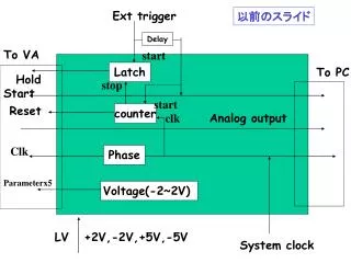
CC Hardware Structure MCH TCLKA Bunch Clock FEE Clock (99MHz) TCLKB Trig (Start) RX17 Telegram Data TX17 Telegram Clock Timing Receiver RX18 CC Master CC Slave Reset TX18 Spare RX19 TX19 Command Ext Clock RX20 Veto Ext Trig TX20 Status = Signal Source • Telegrams are to be sent as a data and strobe/clock pair from the TR
CC Firmware Structure • C&C firmware structure
Current Status • Just received the XUPV5 development board • Virtex 5 LX110T FPGA on board • Various clock sources • Differential and single-ended expansion headers • Going to use XUPV5 for firmware prototyping • Until DAMC2, TR, xTCA crate available • Daughtercard designs for initial testing ready • 2 different versions • Version A – simple I/O functionality – Transmit/Receive on the same card • Version B – simple I/O + standalone clock generation + TR interface • Trying to arrange EDA tool usage with RAL • Cadence Allegro design flow • Telegram data protocol • Suggesting a protocol similar to the FAST commands
Current Status • Daughtercard designs
C&C firmware • Fast Message Generation – Start and Stop messages
Outstanding Issues • Telegram data protocol should be finalised • Exact type of inputs to the TR – standard signals to the CC for non-XFEL sources • Next version of DAMC2 – changes to TCLKA/B according to CC requirements • Bi-directional TCLKA/B • RTM design considerations • Specs needed – Size, connector etc. • How to support IPMI • Power supply circuitry • Any other
Future Plans • Getting the daughtercards ready • Firmware development • Initial in-house testing • Expecting DAMC2 • RTM design