
Digital Back-end for KAT
E N D
Presentation Transcript
Digital Back-end for KAT June 2006 Alan Langman
Outline • Overview of the Karoo Array Telescope • Location • Performance • Operation • Requirements for Digital Back-end • Digital Back-end architecture • Implementation • Hardware • Firmware
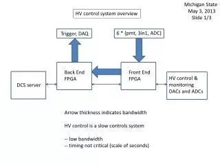
KAT System Overview Station array Front-end receiver Station Controller Cluster Horn (7 HV) Station Processor Dish X (20 antennas X7(HV) beams) Positioner Observation data Operations centre RF/Cntrl Karoo Site Cape Town Site Data products User (Scientist) Remote
DSP Strategy • Develop a low cost generic Digital Signal Processing Backend for KAT • Scalable and Upgradeable • Designed for Logistic Support (remote operation) • Develop a signal processing framework that can be used for RA DSP algorithm development, verification, performance and cost predictions. • Strong unified (algorithm development, hardware and software implementation) testing framework.
Digital Backend Requirements • B=256MHz, 65K channels, 8 bit • Correlation + Beamforming • Connected element - 190 Baselines • Transient Signal support • RFI mitigation (excision) • Spectral and Continuum Imaging • 10-60s dump rate • FX (Polyphase) Correlator • Custom hardware, FPGA reconfigurable logic
Design Considerations • Mechanical (backplane and cabling) • Timing Synchronization - PXIe • ADC - National/Atmel - Dual 1.5GS/s • Xilinx vs Altera <- Possibly support both • 10Ge vs Infiniband vs Myrinet • Design for changing requirements • Firmware Development/Deployment • Control and Monitoring
Algorithm Development • Matlab/Simulink System Generator/BEE2 design process • Mathematical modeling • Firmware generation • Testing Framework linked Matlab/Simulink • Reusable, rapid application development • CASPER collaboration
Embedded Software • Each board has PowerPC processor • Runs Linux/L4 • Management, control, configuration,testing • Simple scriptable telnet interface
Roadmap • Experimental Prototype Demonstrator (XDM) • July 2007 • Single dish 7HV horns link to 26m HartRao • Advanced Prototype Demonstrator (ADM) • Jan 2008 • Single dish 7HV horns link to 26m HartRao • Full KAT Digital Back-end • Dec 2009
Conclusion • Building Digital Backend - 256MHz, 190 baseline, FX, beamformer • Following CASPER group, HERC - focusing on ‘”software” IP delaying optimization of hardware • XDM, ADM, KAT • Operational Dec 2009