Download
1 / 61
610 likes | 787 Views
Chap 3 – Frame Relay Learning Objectives. Describe the fundamental concepts of Frame Relay technology in terms of Enterprise WAN services including Frame Relay operation, Frame Relay implementation requirements, Frame Relay maps, and LMI operation.

E N D
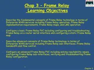
Chap 3 – Frame Relay Learning Objectives • Describe the fundamental concepts of Frame Relay technology in terms of Enterprise WAN services including Frame Relay operation, Frame Relay implementation requirements, Frame Relay maps, and LMI operation. • Configure a basic Frame Relay PVC including configuring and troubleshooting Frame Relay on a router serial interface and configuring a static Frame Relay map. • Describe advanced concepts of Frame Relay technology in terms of Enterprise WAN services including Frame Relay sub-interfaces, Frame Relay bandwidth and flow control. • Configure an advanced Frame Relay PVC including solving reachability issues, configuring Frame Relay sub-interfaces, verifying and troubleshooting Frame Relay configuration.
Requirement for Frame Relay • A dedicated line provides little practical opportunity for a one-to-many connection without getting more lines from the network provider. • Inefficient use of bandwidth. • Cost increases are proportional to the distance between sites.
Requirement for Frame Relay • Frame Relay customers only pay for the local loop, and for the bandwidth they purchase from the network provider. • Distance between nodes is not important. • Efficient use of bandwidth as Frame Relay shares bandwidth across a larger base of customers.
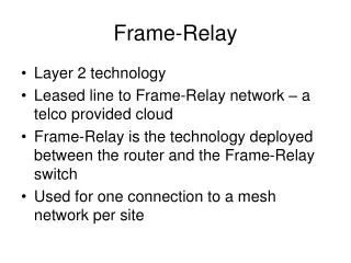
Frame Relay • Frame Relay is an ITU-T and ANSI standard. • Frame Relay is a packet-switched, connection-oriented, WAN service, operating at the data link layer of the OSI reference model. • Frame Relay uses a subset of the high-level data-link control (HDLC) protocol called Link Access Procedure for Frame Relay (LAPF). • Frames carry data between user devices called data terminal equipment (DTE), and the data communications equipment (DCE) at the edge of the WAN
Frame Relay Overview Frame Relay is used between the customer premises equipment (CPE) device and the Frame Relay switch. It does not affect how packets get routed within the Frame Relay ‘cloud’.
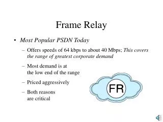
Frame Relay Overview • Packet Switched • STDM • Uses Virtual Circuits through the network • Bandwidth is not allocated until required • Buffering and congestion control mechanisms • Relies on upper layer protocols (e.g. TCP) for error recovery • Supports data rates up to 45Mbps
Terminology • The connection through the Frame Relay network between two DTEs is called a VC (Virtual Circuit). • Virtual circuits may be established dynamically by sending signaling messages to the network. In this case they are called SVC (Switched Virtual Circuits) • Generally PVC (Permanent Virtual Circuits) that have been pre-configured by the carrier are used. The switching information for a VC is stored in the memory of the Frame relay switches and/or infrastructure switches.
A B C D Data Link Connection Identifier (DLCI) 121 0 579 432 119 319 • Virtual circuits sharing a single access line can be distinguished because each VC has a separate DLCI. • The DLCI is stored in the address field of every frame transmitted, and usually has only local significance.
Multiple Virtual Circuits DLCI 101 Frame Relay Network DLCI 100 DLCI 300 DLCI 200 DLCI 201 DLCI 301 • The Frame Relay Access Device (FRAD) or router connected to the Frame Relay network may have multiple VCs connecting it to various endpoints. • Multiple VCs on a single physical line are distinguished because each VC has its own DLCI.
Frame Relay Stack Layered Support IP Packet Layer 3 Flag Address Data FCS Flag Layer 2 Layer 1 Line Coding = 10101010100100101011111100101
Frame Relay Header Flag Address Data FCS Flag • DLCI - Data Link Connection Identifier • DE – Discard Eligible • FECN – Forward Explicit Congestion Identifier • BECN- Backwards Explicit Congestion Identifier
Star Topology In a hub and spoke topology the location of the hub is chosen to give the lowest leased line cost
Frame Relay Star Topology HUB Because Frame Relay tariffs are not distance related, the hub does not need to be in the geographical centre of the network.
Full-Mesh Topology A full mesh topology is chosen when services to be accessed are geographically dispersed and highly reliable access to them is required
Frame Relay Partial Mesh With partial mesh, there are more interconnections than required for a star arrangement, but not as many as for a full mesh
= E1 E1 Frame Relay bandwidth and flow control • Local access rate or port speed – This is the clock speed or port speed of the connection or local loop to the Frame Relay cloud. It is the rate at which data travels into or out of the network, regardless of other settings. • Committed Information Rate (CIR) – This is the rate, in bits per second, at which the Frame Relay switch agrees to transfer data. The rate is usually averaged over a period of time, referred to as the Committed Time Interval (Tc).
Frame Relay bandwidth and flow control • Committed Burst Information Rate (CBIR) is a negotiated rate above the CIR which the customer can use to transmit for short burst. • It allows traffic to burst to higher speeds, as available network bandwidth permits. • However, it cannot exceed the port speed of the link. A device can burst up to the CBIR and still expect the data to get through. • The duration of a burst transmission should be short, less than three or four seconds. If long bursts persist, then a higher CIR should be purchased.
Frame Relay Bursting • Frames submitted above the CIR marked as Discard Eligible (DE) in the frame header, indicating that they may be dropped if there is congestion or there is not enough capacity in the network
Frame Relay Header Flag Address Data FCS Flag • DE – Discard Eligible • FECN – Forward Explicit Congestion Identifier • BECN- Backwards Explicit Congestion Identifier
= E1 E1 Frame Relay bandwidth and flow control • Forward Explicit Congestion Notification (FECN) – When a Frame Relay switch recognizes congestion in the network, it sends an FECN packet to the destination device, indicating that congestion has occurred. • Backward Explicit Congestion Notification (BECN) – When a Frame Relay switch recognizes congestion in the network, it sends a BECN packet to the source router, instructing the router to reduce the rate at which it is sending packets.
= E1 E1 Frame Relay bandwidth and flow control • Discard eligibility (DE) bit is set on the traffic that was received after the CIR was met – i.e. Burst Excess (BE). • Data frames with the DE bit set are normally delivered. However, in periods of congestion, the Frame Relay switch will drop packets with the DE bit set first.
Frame Relay bandwidth • Several factors determine the rate at which a customer can send data on a Frame Relay network. foremost in limiting the maximum transmission rate is the capacity of the local loop to the provider. • If the local loop is an E1, no more than 2.048 Mbps can be sent. In Frame Relay terminology, the speed of the local loop is called the localaccess rate. • Providers use the CIR parameter to provision network resources and regulate usage. • For example, a company with an E1 connection to a packet-switched network (PSN) may agree to a CIR of 1024 Kbps. This means that the provider guarantees 1024 Kbps of bandwidth to the customer’s link at all times.
Frame Relay bandwidth • Typically, the higher the CIR, the higher the cost of service. • Customers can choose the CIR that is most appropriate to their bandwidth needs, as long as the CIR is less than or equal to the local access rate. • If the CIR of the customer is less than the local access rate, the customer and provider agree on whether bursting above the CIR is allowed. • If the local access rate is E1 or 2.048 Mbps, and the CIR is 1024 Kbps, half of the potential bandwidth (as determined by the local access rate) remains available.
Frame Relay bandwidth • Many providers allow their customers to purchase a CIR of 0 (zero) - This means that the provider does not guarantee any throughput. • In practice, customers usually find that their provider allows them to burst over the 0 (zero) CIR virtually all of the time. • If a CIR of 0 (zero) is purchased, carefully monitor performance in order to determine whether or not it is acceptable. • Frame Relay allows a customer and provider to agree that under certain circumstances, the customer can “burst” over the CIR. • Since burst traffic is in excess of the CIR, the provider does not guarantee that it will deliver the frames.
Network Address Mapping • A mapping is needed in each FRAD or router between a data link layer Frame Relay address (DLCI) and a network layer address, such as an IP address. • The DLCI for each VC must be associated with the network address of its remote router. This information can be configured statically by using map commands. • The DLCI can also be configured automatically using Inverse ARP.
LMI – Local Management Interface • LMI is a signaling standard between the DTE and the Frame Relay switch. • LMI is responsible for managing the connection and maintaining the status between devices. • Cisco supports 3 LMI standards – ANSI, Q933a, Cisco LMI includes: • A keepalive mechanism, which verifies that data is flowing. • A multicast mechanism, which provides the network server (router) with its local DLCI. • Multicast addressing, which can give DLCIs global rather than local significance in Frame Relay networks (not common). • A status mechanism, which provides an ongoing status on the DLCIs known to the switch.
LMI – Local Management Interface • There are three types of LMI, none of which is compatible with the others. • Cisco, StrataCom, Northern Telecom, and Digital Equipment Corporation (Gang of Four) released one type of LMI, while the ANSI and the ITU-T each released their own versions. • The LMI type must match between the provider Frame Relay switch and the customer DTE device. Frame Relay Network LMI
LMI – Local Management Interface • In Cisco IOS releases prior to 11.2, the Frame Relay interface must be manually configured to use the correct LMI type. • If using Cisco IOS Release 11.2 or later, the router attempts to automatically detect the type of LMI used by the provider switch. • This automatic detection process is called LMI autosensing. Frame Relay Network LMI
LMI – Local Management Interface • The 10-bit DLCI field allows VC identifiers 0 through 1023. The LMI extensions reserve some of these identifiers. This reduces the number of permitted VCs. • LMI messages are exchanged between the DTE and DCE using these reserved DLCIs.
LMI Extensions In addition to the Frame Relay protocol functions for transferring data, the Frame Relay specification includes optional LMI extensions that are extremely useful in an Internetworking environment. Some of the extensions include: • VC status messages - Provide information about PVC integrity by communicating and synchronizing between devices, periodically reporting the existence of new PVCs and the deletion of already existing PVCs. VC status messages prevent data from being sent into black holes (PVCs that no longer exist). • Multicasting - Allows a sender to transmit a single frame that is delivered to multiple recipients. Multicasting supports the efficient delivery of routing protocol messages and address resolution procedures that are typically sent to many destinations simultaneously. • Global addressing - Gives connection identifiers global rather than local significance, allowing them to be used to identify a specific interface to the Frame Relay network. Global addressing makes the Frame Relay network resemble a LAN in terms of addressing, and ARPs perform exactly as they do over a LAN. • Simple flow control - Provides for an XON/XOFF flow control mechanism that applies to the entire Frame Relay interface. It is intended for those devices whose higher layers cannot use the congestion notification bits and need some level of flow control.
R1 Frame Relay Address Mapping DLCI 101 DLCI 102 • R1 connects to the Frame Relay network, it sends an LMI status inquiry message (75) to the network. • Network replies with an LMI status message (7D) containing details of every VC configured on the access link. • If the router needs to map the VCs to network layer addresses, it sends an Inverse ARP message on each VC. • The Inverse ARP message includes the network layer address of the router, so the remote DTE, or router, can also perform the mapping.
Frame Relay Network DLCI 101 DLCI 102 Configuring Frame Relay maps Hub City Spokane 172.16.1.2 172.16.1.1 • If the environment does not support LMI autosensing and Inverse ARP, a Frame Relay map must be manually configured. • Once a static map for a given DLCI is configured, Inverse ARP is disabled on that DLCI. HubCity(config)# interface serial 0 HubCity(config-if)# frame-relay map ip 172.16.1.1 101 broadcast Spokane(config)# interface serial 0 Spokane(config-if)# frame-relay map ip 172.16.1.2 102 broadcast
Frame Relay Network DLCI 101 DLCI 102 Inverse ARP Hub City Spokane 172.16.1.2 172.16.1.1 HubCity# show frame-relay map Serial0 (up): ip 172.16.1.1 dlci 101, dynamic, broadcast, status defined, active • dynamic refers to the router learning the IP address via Inverse ARP • DLCI 101 is configured on the Frame Relay Switch by the provider.
Frame Relay Network DLCI 101 DLCI 102 Inverse ARP Limitations Hub City Spokane 172.16.1.2 172.16.1.1 • Inverse ARP only resolves network addresses of remote Frame-Relay connections that are directly connected via frame-relay nodes. • Inverse ARP does not work with Hub-and-Spoke connections. • Dynamic address mapping is enabled by default for all protocols enabled on a physical interface. • If the Frame Relay environment supports LMI autosensing and Inverse ARP, dynamic address mapping takes place automatically.
DLCI 201 DLCI 102 Frame Relay Configuration R2 DLCI 203 S0/0/0 10.1.1.2 / 24 S0/0/0 10.1.1.1 / 24 S0/0/0 10.1.1.3 / 24 DLCI 302 R3 R1 DLCI 103 DLCI 301 Fa0/1 192.168.10.1 / 24 Fa0/1 192.168.30.1 / 24 • Default Frame Relay encapsulation enabled on supported interfaces is the Cisco encapsulation. • Use Cisco encapsulation if connecting to another Cisco router, use IETF if connecting to non-Cisco devices.
DLCI 201 DLCI 102 Frame Relay Configuration R2 DLCI 203 S0/0/0 10.1.1.2 / 24 S0/0/0 10.1.1.1 / 24 S0/0/0 10.1.1.3 / 24 DLCI 302 R3 R1 DLCI 103 DLCI 301 Fa0/1 192.168.10.1 / 24 Fa0/1 192.168.30.1 / 24 Static Map • If the environment does not support LMI autosensing and Inverse ARP, a Frame Relay map must be manually configured. • Once a static map for a given DLCI is configured, Inverse ARP is disabled on that DLCI. .0
Reachability issues with routing updates • An None Broadcast Multiple Access (NBMA) network is a multi-access network, which means more than two nodes can connect to the network. • Frame Relay is a NBMA, and its nodes cannot see broadcasts of other nodes unless they are directly connected by a virtual circuit. • This means that Branch A cannot directly see the broadcasts from Branch B, because they are connected using a hub and spoke topology.
Reachability issues with routing updates • The Central router must receive the routing update broadcast from Branch A and then send its own update broadcast to Branch B & C. • In this example, there are problems with routing protocols because of the split horizon rule. • Split Horizon prohibits routing updates received on an interface from exiting that same interface.
Frame Relay Network 172.30.3.2/24 S0 DLCI 101 172.30.3.1/24 S3 DLCI 100 • Use of multiple point-to-point serial interfaces solves the problem of split-horizon, as routing updates are not being sent from the same physical interface. • Expensive to implement, as multiple serial interfaces and point-to-point connections are required. 172.30.2.2/24 S0 DLCI 201 172.30.2.1/24 S2 DLCI 200 172.30.1.1/24 S0 DLCI 300 172.30.1.2/24 S0 DLCI 301
Point-to-Point Sub-interface • A single point-to-point sub-interface is used to establish one PVC connection to another physical interface or sub-interface on a remote router. • In this case, each pair of the point-to-point routers is on its own subnet and each point-to-point sub-interface would have a single DLCI. • In a point-to-point environment, each sub-interface is acting like a point-to-point interface. Therefore, routing update traffic is not subject to the split-horizon rule.
Frame Relay Network 172.30.3.2/24 S0 DLCI 101 Interface S0 • Point-to-point sub-interfaces are equivalent to using multiple physical “point to point” interfaces. 172.30.3.1/24 DLCI 100 S0.100 172.30.2.2/24 S0 DLCI 201 172.30.2.1/24 DLCI 200 S0.200 S0.300 172.30.1.1/24 DLCI 300 172.30.1.2/24 S0 DLCI 301
172.30.3.2/24 S0 DLCI 101 Interface S0 172.30.3.1/24 DLCI 100 S0.100 S0.200 S0.300 Point-to-point Sub-interfaces Router(config)# interface Serial 0 Router(config-if)# encapsulation frame-relay ietf Router(config-if)#frame-relay lmi-type ansi Router(config-if)# interface Serial0.100 point-to-point Router(config-if)# ip address 172.30.3.1 255.255.255.0 Router(config-subif)# frame-relay interface-dlci 100 Router(config-subif)# exit Router(config-if)# interface Serial0.200 point-to-point Router(config-if)# ip address 172.30.2.1 255.255.255.0 Router(config-subif)# frame-relay interface-dlci 200 172.30.2.2/24 S0 DLCI 201 172.30.2.1/24 DLCI 200 172.30.1.1/24 DLCI 300 172.30.1.2/24 S0 DLCI 301
Point-to-point Sub-interfaces Frame-Relay service supplies multiple PVCs over a single physical interface and point-to-point sub-interfaces subdivide each PVC as if it were a physical point-to-point interface. Point-to-point sub-interfaces are like conventional point-to-point interfaces and do not need or allow: • Inverse-ARP • Frame-relay map statements • Multiple DLCIs for a sub-interface Point-to-point sub-interfaces completely bypass the local DLCI to remote network address mapping issue.
Multipoint Sub-interface • A single multipoint sub-interface is used to establish multiple PVC connections to multiple physical interfaces or sub-interfaces on remote routers. • All the participating interfaces would be in the same subnet. • The sub-interface acts like an NBMA Frame Relay interface so routing update traffic is subject to the split-horizon rule.
Frame Relay Network 172.30.1.2/24 S0 DLCI 101 Interface S0 Point-to-Point • Multipoint sub-interfaces are equivalent to using multiple physical “hub to spoke” interfaces DLCI 100 S0.1 172.30.1.1/24 172.30.1.3/24 S0 DLCI 201 DLCI 200 DLCI 300 Point-to-Point Multipoint 172.30.1.4/24 S0 DLCI 301 Point-to-Point
Frame Relay Network 172.30.1.2/24 S0 DLCI 101 Interface S0 Point-to-Point • Router(config)# interface Serial 0 • Router(config-if)# encapsulation frame-relay ietf • Router(config-if)# interface Serial0.123 multipoint • Router(config-if)# ip address 172.30.1.1 255.255.255.0 • Router(config-subif)# frame-relay interface-dlci 100 • Router(config-subif)# frame-relay interface-dlci 200 • Router(config-subif)# frame-relay interface-dlci 300 DLCI 100 S0.1 172.30.1.1/24 172.30.1.3/24 S0 DLCI 201 DLCI 200 DLCI 300 Point-to-Point Multipoint 172.30.1.4/24 S0 DLCI 301 Point-to-Point
Multipoint Sub-interfaces Share many of the same characteristics as a physical Frame-Relay interface. With multipoint sub-interface you can have: • Multiple DLCIs assigned to it. • Frame-relay map & interface dlci statements • Inverse-ARP Which is the opposite of point-to-point interfaces.
Mixing Inverse ARP and Frame Relay Map Statements Frame-Relay Map Statement Rule: When a Frame-Relay map statement is configured for a particular protocol (e.g. IP or IPX) Inverse-ARP will be disabled for that specific protocol, not only for the DLCI referenced in the Frame-Relay map statement.
Frame Relay Network 172.30.1.2/24 S0 DLCI 101 Interface S0 Point-to-Point DLCI 100 S0.1 172.30.1.1/24 172.30.1.3/24 S0 DLCI 201 DLCI 200 DLCI 300 Point-to-Point Multipoint 172.30.1.4/24 S0 DLCI 301 Point-to-Point Solution: Do not mix IARP with Frame Relay maps statements. If need be use Frame-Relay map statements instead of IARP.
Frame Relay Sub-interfacesSummary • Point-to-Point • Sub-interfaces act as a leased line • Each point-to-point sub-interface requires its own subnet • Applicable to hub and spoke topologies • Multipoint • Sub-interfaces act as NBMA network, so they do not resolve the split horizon issue • Can save address space because it uses a single subnet • Applicable to partial-mesh and full-mesh topology