4 Introduction to Process Analysis and Selection
2.59k likes | 3.04k Views
4 Introduction to Process Analysis and Selection.

4 Introduction to Process Analysis and Selection
E N D
Presentation Transcript
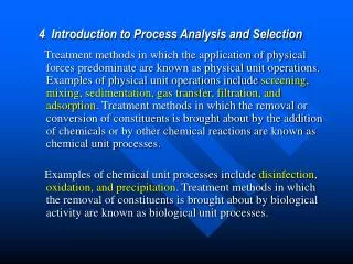
4 Introduction to Process Analysis and Selection Treatment methods in which the application of physical forces predominate are known as physical unit operations. Examples of physical unit operations include screening, mixing, sedimentation, gas transfer, filtration, and adsorption. Treatment methods in which the removal or conversion of constituents is brought about by the addition of chemicals or by other chemical reactions are known as chemical unit processes. Examples of chemical unit processes include disinfection, oxidation, and precipitation. Treatment methods in which the removal of constituents is brought about by biological activity are known as biological unit processes.
Unit operations and processes occur in a variety of combinations in treatment flow diagrams. The rate at which reactions and conversions occur, and the degree of their completion, is generally a function of the constituents involved, the temperature, and the type of reactor (i.e., container or tank in which the reactions take place). The fundamental basis for the analysis of the physical, chemical, and biological unit operations and processes used for wastewater treatment is the materials mass balance principle in which an accounting of mass is made before and after reactions and conversions have taken place.
Fig. 4-1 Overview of a biological nutrient removal(BNR) wastewater-treatment plant
4-1 Reactors used for the Treatment of Wastewater Types of Reactors Fig. 4-2 Definition sketch for various types of reactors used for wastewater treatment The principal types of reactors used for the treatment of wastewater, are (1) the batch reactor, (2) the complete-mix reactor (also known as the continuous-flow stirred-tank reactor (CFSTR) in the chemical engineering literature), (3) the plug-flow reactor (also known as a tubular-flow reactor), (4) complete-mix reactors in series, (5) the packed-bed reactor, (6) the fluidized-bed reactor.
Batch Reactor In the batch reactor, flow is neither entering nor leaving the reactor (i.e, flow enters, is treated, and then is discharged, and the cycle repeats). The BOD test is carried out in a batch reactor that are often used to blend chemicals or to dilute concentrated chemicals.
Complete-Mix Reactor Fluid particles leave the reactor in proportion to their statistical population. Complete mixing can be accomplished in round or square reactors if the contents of the reactor are uniformly and continuously redistributed. The actual time required to achieve completely mixed conditions will depend on the reactor geometry and the power input.
Plug-Flow Reactor Fluid particles pass through the reactor with little or no longitudinal mixing and exit from the reactor in the same sequence in which they entered. The particles retain their identity and remain in the reactor for a time equal to the theoretical detention time.
Complete-Mix Reactors in Series The series of complete-mix reactors is used to model the flow regime that exists between the ideal hydraulic flow patterns corresponding to the complete-mix and plug-flow reactors. If the series is composed of one reactor, the complete-mix regime prevails. If the series consists of an infinite number of reactors in series, the plug-flow regime prevails.
Packed-Bed Reactors Dosing can be continuous or intermittent (e.g., trickling filter). The packing material in packed-bed reactors can be continuous or arranged in multiple stages, with flow from one stage to another. Fluidized-Bed Reactor The fluidized-bed reactor is similar to the packed-bed reactor in many respects, but the packing material is expanded by the upward movement of fluid (air or water) through the bed. The expanded porosity of the fluidized-bed packing material can be varied by controlling the flowrate of the fluid.
Application of Reactors Tab. 4-1 Principal applications of reactor types used for wastewater treatment Operational factors that must be considered in the selection of the type of reactor or reactors to be used in the treatment process include (1) the nature of the wastewater to be treated, (2)the nature of the reaction (i.e., homogeneous or heterogeneous), (3) the reaction kinetics governing the treatment process, (4) the process performance requirements, (5)local environmental conditions. In practice, the construction costs and operation and maintenance costs also affect reactor selection.
Ideal Flow in Complete-Mix and Plug-Flow Reactors The ideal hydraulic flow characteristics of complete-mix and plug-flow reactors are illustrated on Fig. 4-3 in which dye tracer response craves are presented for pulse (slug-dose) and step inputs (continuous injection). Fig. 4-3 Output tracer response curves from reactors subject to pulse and step inputs of a tracer
Nonideal Flow in Complete-Mix and Plug-Flow Reactors. In practice the flow in complete-mix and plug-flow reactors is seldom ideal. It is the precautions taken to minimize these effects that are important.
4-2 Mass-balance Analysis The fundamental approach used to study the hydraulic flow characteristics of reactors and to delineate the changes that take place when a reaction is occurring in a reactor (e.g., a container), or in some definable portion of a body of liquid, is the mass-balance analysis.
The Mass-Balance Principle The mass-balance analysis is based on the principle that mass is neither created nor destroyed, but the form of the mass can be altered (e.g., liquid to a gas). The mass-balance analysis affords a convenient way of defining what occurs within treatment reactors as a function of time. Fig. 4-4 Definition sketch for the application of materials mass-balance analysis for a complete-mix reactor with inflow and outflow. The presence of a mixer is used to represent symbolically the fact the contents of the reactor are mixed completely. The photo is of a typical complete-mix activated sludge reactor used for the biological treatment of wastewater.
The system boundary is drawn to identify all of the liquid and constituent flows into and out of the system For a given reactant, the general mass-balance analysis is given by 1. General word statement 2. The corresponding simplified word statement A positive sign is used for the rate-of-generation term because the necessary sign for the operative process is past of the rate expression (e.g., rc = -kC for a decrease in the reactant or rc = + kC for all increase in the reactant).
Preparation of Mass Balances 1. Prepare a simplified schematic or flow diagram of the system or process 2. Draw a system or control volume boundary to define the limits . Proper selection of the system or control volume boundary is extremely important because, in many situations, it may be possible to simplify the mass-balance computations. 3. List all of the pertinent data and assumptions 4. List all of the rate expressions for the biological or chemical reactions 5. Select a convenient basis It is recommended that the above steps be followed routinely.
Application of the Mass-Balance Analysis To apply a mass-balance analysis to the liquid contents of the reactor shown on Fig. 4-4, it will be assumed that: 1. The volumetric flowrate into and out of the control volume is constant. 2. The liquid within the control volume is not subject to evaporation (constant volume). 3. The liquid within the control volume is mixed completely. 4. A chemical reaction involving a reactant A is occurring within the reactor. 5. The rate of change in the concentration of the reactant A that is occurring within the control volume is governed by a first-order reaction (rc = -kC ).
Using the above assumptions, the mass balance can be formulated as follows 1. Simplified word statement 2. Symbolic representation Before attempting to solve any mass-balance expression, a unit check should always be made to assure that units of the individual quantities are consistent.
Steady-State Simplification Fortunately, in most applications in the field of wastewater treatment, the solution of mass-balance equations, such as the one given by the equations, can be simplified by noting that the steady-state(i.e., long-term) concentration is of principal concern. If it is assumed that only the steady-state effluent concentration is desired, then above equation can be simplified by noting that, under steady-state conditions, the rate accumulation is zero (dC/dt = 0).
4-3 Analysis of Nonideal Flow in Reactors Using Tracers Because of a lack of appreciation for the hydraulics of reactors, many of the treatment plants that have been built do not perform hydraulically as designed.
Fig. 4-5 Definition sketch for short circuiting caused by (a)density currents caused by temperature differences; (b)wind circulation patterns; (c)inadequate mixing; (d)fluid advection(平流) and dispersion
Factors leading to nonideal flow in reactors include: 1. Temperature differences. In complete-mix and plug-flow reactors, nonideal flow (short circuiting) can be caused by density currents due to temperature differences. When the water entering the reactor is colder or warmer than the water in the tank, a portion of the water can travel to the outlet along the bottom of or across the top of the reactor without mixing completely (see Fig. 4-5a). 2. Wind-driven circulation patterns. In shallow reactors, wind-circulation patterns can be set up that will transport a portion of the incoming water to the outlet in a fraction of the actual detention time (see Fig. 4-5b).
3. Inadequate mixing. Without sufficient energy input, portions of the reactor contents may not mix with the incoming water (see Fig. 4-5c). 4. Poor design. Depending on the design of the inlet and outlet of the reactor relative to the reactor aspect ratio, dead zones may develop within the reactor that will not mix with the incoming water (see Fig. 4-5d). 5. Axial dispersion in plug-flow reactors. In plug-flow reactors the forward movement of the tracer is due to advection and dispersion. Advection is the term used to describe the movement of dissolved or colloidal material with the current velocity. Dispersion is the term used to describe the axial and longitudinal transport of material brought about by velocity differences, turbulent eddies, and molecular diffusion.
Need for Tracer Analysis The use of dyes and tracers for measuring the residence time distribution curves is one of the simplest and most successful methods now used to assess the hydraulic performance of full-scale reactors. Important applications of tracer studies include (1) the assessment of short circuiting in sedimentation tanks and biological reactors, (2) the assessment of the contact time in chlorine contact basins,
(3) the assessment of the hydraulic approach conditions in UV reactors, and (4) the assessment of flow patterns in constructed wetlands and other natural treatment systems. Tracer studies are also of critical importance in assessing the degree of success that has been achieved with corrective measures.
Types of Tracers Over the years, a number of tracers have been used to evaluate the hydraulic performance of reactors. Important characteristics for a tracer include : (1)The tracer should not affect the flow (should have essentially the same density as water when diluted). (2)The tracer must be conservative so that a mass balance can be performed.
(3)It must be possible to inject the tracer over a short time period. (4)The tracer should be able to be analyzed conveniently. (5)The molecular diffusivity of the tracer should be low. (6)The tracer should not be absorbed on or react with the exposed reactor surfaces. (7)The tracer should not be absorbed on or react with the particles in wastewater.
Dyes and chemicals that have been used successfully in tracer studies include congo-red, fluorescein, fluorosilicic acid (H2SiF6), hexafluoride gas (SF6), lithium chloride (LiCl), Pontacyl Brilliant Pink B, potassium, potassium permanganate, rhodamine WT, and sodium chloride (NaCl). Pontacyl Brilliant Pink B (the acid form of rhodamine WT) is especially useful in the conduct of dispersion studies because it is not readily adsorbed onto surfaces.
Because fluorescein, rhodamine WT, and Pontacyl Brilliant Pink B can be detected at very low concentrations using a fluorometer , they are the dye tracers used most commonly in the evaluation of wastewater-treatment facilities. Lithium chloride is commonly used for the study of natural systems. Sodium chloride, used commonly in the past, has a tendency to form density currents unless mixed. Hexafluoride gas (SF6) is used most commonly for tracing the movement of groundwater.
Conduct of Tracer Tests Fig 4-6 Schematic of setup used to control tracer studies of plug-flow reactors (a)slug of tracers added to flow; (b)continuous input of tracer added to flow. Tracer response curve is measured continuously.
Analysis of Tracer Response Curves Fig. 4-8 Typical tracer response curves: two different types of circular clarifiers and open channel UV disinfection system
4-4 Reactions, Reaction Rates, and Reaction Rate Coefficients The stoichiometry of reaction refers to the definition of the quantities of chemical compounds involved in a reaction. The rate expressions discussed in this section will be integrated with the hydraulic characteristics of the reactors, discussed previously, to define treatment kinetics. Types of Reactions The two principal types of reactions that occur in wastewater treatment are classified as homogeneous and heterogeneous (non-homogeneous).
Homogeneous Reactions In homogeneous reactions, the reactants are distributed uniformly throughout the fluid so that the potential for reaction at any point within the fluid is the same, Homogeneous reactions are usually carried out in the batch, complete-mix, and plug-flow reactors .
Examples of irreversible reactions are a. Simple reactions A——>B A + A——> C aA + bB ——> C b. Parallel reactions A + B ——> C A + B ——>D c. Consecutive reactions A + B ——> C A + C——> D Examples of reversible reactions are A <——> B A + B <——> C + D
Heterogeneous Reactions Heterogeneous reactions occur between one or more constituents that can be identified with specific sites, such as those on an ion exchange resin . These reactions are more difficult to study because a number of interrelated steps may be involved. The typical sequence of these steps is as follows: 1. Transport of reactants from the bulk fluid to the fluid-solid interface (external surface of catalyst particle)
2. Intraparticle transport of reactants into the catalyst particle (if it is porous) 3. Adsorption of reactants at interior sites of the catalyst particle 4. Chemical reaction of adsorbed reactants to adsorbed products (surface reaction) 5. Desorption of adsorbed products 6. Transport of products from the interior sites to the outer surface of the catalyst particle
Process Comments Constituents affected Adsorption/ desorption Many chemical constituents tend to attach or sorb onto solids. The implication for wastewater discharges is that a substantial fraction of some toxic chemicals is associated with the suspended solids in the effluent. Adsorption combined with solids settling results in the removal from the water column of constituents that might not otherwise decay Metal, trace organics, NH4+, PO43- Rate Expressions Used in Environmental ModelingTab. 4-2 Constituent transformation and removal processes(i.e., fate processes) in the environment
Algal synthesis The synthesis of algal cell tissue using the nutrients found in wastewater NH4+,NO3-,PO43-,pH, etc Bacterial conversion Bacterial conversion (both aerobic and anaerobic) is the most important process in the transformation of constituents released to the environment. The exertion of BOD and NOD is the most common example of bacterial conversion encountered in waterquality management. The depletion of oxygen in the aerobic conversion of organic wastes is also known as deoxygenation. Solids discharged with treated wastewater are partly organic. Upon settling to the bottom, they decompose bacterially either anaerobically or aerobically, depending on local conditions. The bacterial transformation of toxic organic compounds is also of great significance. BOD5,nitrification, denitrification, sulfate reduction, anaerobic fermentation (in bottom sediments), conversion of priority organic pollutants,etc.
Chemical reactions Important chemical reactions that occur in the environment include hydrolysis, photochemical, and oxidation-reduction reactions. Hydrolysis reactions occur between contaminants and water. Chemical disinfection, decomposition of organic compounds, specific ion exchange, element substitution. Filtration Removal of suspended and colloidal solids by straining (mechanical and chance contact), sedimentation, interception, impaction, and adsorption. TSS, colloidal particles Flocculation Flocculation is the term used to describe the aggregation of smaller particles into larger particles that can be removed by sedimentation and filtration. Flocculation is brought about by Brownian motion, differential velocity gradients, and differential settling in which large particles overtake smaller particles and form larger particles. Colloidal and small particles
Gas absorption/desorption The process whereby a gas is taken up by a liquid is known as absorption. For example, when the dissolved oxygen concentration in a body of water with a free surface is below the saturation concentration in the water, a net transfer of oxygen occurs from the atmosphere to the water. The rate of transfer (mass per unit time per unit surface area) is proportional to the amount by which the dissolved oxygen is below saturation. The addition of oxygen to water is also known as reaeration. Desorption occurs when the concentration of the gas in the liquid exceeds the saturation value, and there is a transfer from the liquid to the atmosphere. O2,CO2,CH4,NH3,H2S
4-5 Treatment Processes Involving Mass Transfer Unlike mechanical separations, the driving force for the transfer of material is a pressure or concentration gradient). The separation operations are sometimes identified as equilibrium phase separations or equilibrium contact separations, because the transfer of a component will cease when equilibrium conditions prevail. Tab. 4-4 Principal applications of mass transfer operations and processes in wastewater treatment
The most important mass transfer operations in wastewater treatment involve (1) the transfer of material across gas-liquid interfaces as in aeration and in the removal of unwanted gaseous constituents found in wastewater by air stripping, (2) the removal of unwanted constituents from wastewater by adsorption onto solid surfaces such as activated carbon and ion exchange.
Gas-Liquid Mass Transfer The simplest and most commonly used is the two-film theory proposed by Lewis and Whitman (1924). The two-film theory remains popular because, in more than 95 percent of the situations encountered, the results obtained are essentially the same as those obtained with the more complex theories.
The Two-Film Theory The two-film theory is based on a physical model in which two films exist at the gas-liquid interface, as shown on Fig. 4-9. Fig. 4-9 Definition sketch for the two-film theory of gas transfer: (a)absorption;(b)desorption
(a) "absorption," in which a gas is transferred from the gas phase to the liquid phase, (b) "desorption," in which a gas is transferred out of the liquid phase into the gas phase. The two films, one liquid and one gas, provide the resistance to the passage of gas molecules between the bulk-liquid and the bulk-gaseous phases. It is assumed that the concentration and partial pressure in both the bulk liquid and bulk-gas phase are uniform (i.e., mixed completely)
Using Fick's first law, the mass flux for each phase for absorption (gas addition) is written as follows: r= kG(PG-Pi)=kL(Ci-CL) where r=rate of mass transferred per unit area per unit time kG =gas film mass transfer coefficient PG =partial pressure of constituent A in the bulk of the gas phase Pi =partial pressure of constituent A at the interface in equilibrium with concentration Ci of constituent A in liquid
It should be noted that the gas and liquid film mass transfer coefficients depend on the conditions at the interface. The terms (PG - Pi) and (Ci-CL) represent the driving force causing transfer in the gas and liquid phase, respectively. Thus, the degree of mass transport can be enhanced by reducing the thickness of the film, depending on which is the controlling film. If it is assumed that all of the resistance to mass transfer is caused by the liquid film, then the rate of mass transfer can be defined as follows in terms of the overall liquid mass transfer coefficient: r= KL(CS-CL)
Absorption of Gases Fig. 4-10 Definition sketch for the absorption of a gas: (1)under turbulent conditions of gas in the gaseous and liquid phases is uniform; (b)under quiescent conditions.
Liquid-Solid Mass Transfer Adsorption The adsorbate is the substance that is being removed from liquid phase at the interface. The adsorbent is the solid, liquid, or gas phase onto which the adsorbate accumulates. The adsorption process takes place in three steps: macrotransport, microtransport, and sorption. Although adsorption also occurs on the surface of the solid adsorbent and in the macropores and mesopores, the surface area of these parts of most solid adsorbents is so extremely small compared with the surface area of the micropores .
Two important characteristics of the solid adsorbent are (1) its extremely large surface area to volume ratio (2) its preferential affinity for certain constituents in the liquid phase. Granular or powdered activated carbon (GAC or PAC) is used most commonly for the removal of selected constituents from wastewater. A common adsorption isotherm is the Freundlich isotherm.


![[Proposed Change to Selection Process]](https://cdn5.slideserve.com/9674749/proposed-change-to-selection-process-dt.jpg)