Download
1 / 36
400 likes | 1.26k Views
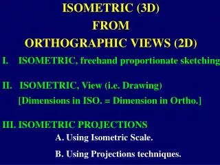
ISOMETRIC (3D) FROM ORTHOGRAPHIC VIEWS (2D). I. ISOMETRIC, freehand proportionate sketching. ISOMETRIC, View (i.e. Drawing) [Dimensions in ISO. = Dimension in Ortho.]. III. ISOMETRIC PROJECTIONS. Using Isometric Scale. Using Projections techniques.

E N D
ISOMETRIC (3D) FROM ORTHOGRAPHIC VIEWS (2D) I. ISOMETRIC, freehand proportionate sketching. • ISOMETRIC, View (i.e. Drawing) • [Dimensions in ISO. = Dimension in Ortho.] III. ISOMETRIC PROJECTIONS • Using Isometric Scale. • Using Projections techniques.
Aim:- Figure-1, shows the F.V. & T.V. of a simple vertical rectangular plane of size LH. Draw its isometric view, for (a) R.H.S.V. & (b) L.H.S.V. b’ a’ H c’ d’ L F.V. a b d c T.V. Figure-1
Q N M P MN, is the base line for isometric axes. PQ, is the isometric axis (vertical) for Fig.1(a) PR, is the isometric axis ( horizontal),for R.H.S.V. for Fig.1(a) at 30º with base line MN. A Note:-The diagonal line a’c’ in ortho. View increases in its iso. View (Fig.1-a), as AC (known as, non isometric line) R B D H L C X Figure-1(a)
Q N M P MN, is the base line for isometric axes. PQ, is the isometric axis (vertical) for Fig.1(b) PS, is the isometric axis ( horizontal),for L.H.S.V. for Fig.1(b) at 30º with base line MN. B Note:-The diagonal line a’c’ in ortho. View decreases in its iso. View (Fig. 1-b), as AC (known as, non isometric line) S A C H L X D Figure-1(b)
Figure shows the Top View of a rectangular plane of 100 x 70. Draw its isometric view i) for R.H.S.V & ii) for L.H.S.V. b a 70 d c 100 T.V.
30 30 X A 70 100 D B C ISOMETRIC VIEW OF THE HORIZONTAL RECTANGULAR PLANE (100 X 70) for its R.H.S.V.
30 30 X B 100 C A 70 D ISOMETRIC VIEW OF THE HORIZONTAL RECTANGULAR PLANE (100 X 70) for its L.H.S.V.
ISOMETRIC VIEW OF SIMPLE PLANES Aim:-Figure shows the F.V.of a cut geometric plane.Draw its Isometric view . (i)For R.H.S.V. & (ii)For L.H.S.V. ? b’ c’ a’ d’ 30 H R g’ f’ e’ L F.V.
? b’ c’ a’ d’ 30 H R g’ f’ e’ L Darken the required arc FD with center C2 A L ? -: Solution :- B AB=a’ b’ ED=EF=R H 30 R2 C Now, only the Quadrant of a circle (L.H.S. upward), is to be drawn using Four center method. R G D R1 C2 F C3 E X C1 C4 30 (i)
? b’ c’ a’ L C d’ 30 B D H ? R A g’ f’ e’ L E 30 H F G X (ii) 30
Aim:-Figure shows the T.V. of a cut geometric plane. Draw its Isometric, (i)For R.H.S.V. d f j i k h 45 45 & (ii) For L.H.S.V. ? b c e R D 30 D1 g a L1 L2 L T.V.
? e b c R d D 30 D1 g a L1 L2 f L j T.V. i 45 45 k h BC=bc= ? ED=EF=R AK=ak=L1 GH=gh=L2 Draw, J I // AG ( at a distance of D1 ) Note :- (1) MJ=KM=D1, as angle jka=45 (2) Angle JKA & Angle IHG are not 45 in isometric. B ? D C 30 D A J 45 M L1 R D1 E K N I H L F 45 L2 X G (i) 30
BC=bc= ? AK=ak=L1 ? d e b c Draw, J I // AG ( at a distance of D1 ) R Note :- (1) MJ=KM=D1, as angle jka=45 (2) Angle JKA & Angle IHG are not 45 in isometric. D f E j 30 i D1 45 45 F D g k h a R L1 L2 L C I G T.V. ? 45 N L2 B H M D1 J L 30 D K 45 L1 X A (ii) 30
Draw the Iso.View of a regular Pentagonal plane of 40mm sides, with one side normal to V.P. & the plane is in H.P. c’ X a’ b’ Y e’ d’ 90° d r s e g 40 c R a D b C q p G 2 D S Q E B 40 A X 3 D P
O’ Draw the Iso.View of a Pentagonal Pyramid, having base sides 40mm, axis 60mm long,when its base is in H.P.with a side of it normal to V.P. 60 X g’ b’ c’ a’ Y d’ e’ d O e 60 c 40 O g R a D C b G 2 D S Q E B 40 A 3 D X P
Aim:- Figure shows the orthographic projections of a cut simple block. Draw its appropriate Pictorial ( Isometric ) view, giving the dimensions. NOTE: The appropriate Isometric will be,considering its R.H.S.V. ( which is not given & is to be added as a missed view).
55 20 A 15 60 55 B 30 20 55 15 15 a d b c R.H.S.V. F.V. Normally, dotted lines are not drawn in Iso. View, unless specifically required to reveal the object perfectly. 2 1 3 T.V. Figure
X 20 ISOMETRIC VIEW 30 1 20 40 A a 2 35 3 15 b B c 15 30 55 d 15 NOTE:- IN R.H.S.MISSED VIEW, THE AREAS, A & B ARE SEEN AND IS DRAWN IN ITS CORROSPONDING SPACE
Figure shows Front View and Top View of a machine parts. Sketch its isometric view & dimension it.
SQ.HOLE OF 20 R25 30° 20 70 30 20 20 10 20 10 20 70 C B A D F.V. b2 a c b1 T.V.
SQ.HOLE OF 20 30° X ISOMETRIC VIEW a 25 10 C c 95 B 20 A b2 b1 20 30 D 25 20 115 50 20
III. A The Front View of the Top Face of a Cube having edges “e” (with one of the body diagonal line, normal D to V.P. ) is to be treated as ISOMETRIC of the Top Face of the Cube (with a side parallel to V.P.) d’ 45° 30° m’ C A All the edges Top face edges, base face edges and 4 vertical edges of the cube are reduced in its isometric view, in the stated condition. c’ a’ M b’ a’d’= f (AD) B
D d’ e x 1/ 2 = 3 / 2 45° 30° m’ C A c’ a’ M i.e. a’d’ = AD x 2/3 b’ a’d’= f (AD) B Cos 30º = a’m’/a’d’ ----- (1) Cos 45º = a’m’/AD ----- (2) From (1) & (2) a’m’ = a’d’ cos30º = AD cos45º i.e. a’d’ = AD cos45º/cos 30 i.e. ISOMETRIC LENGTH = (0.815 x ACTUAL LENGTH)
Aim :Figure shows the F.V & T.V of a stepped block. Draw its ISOMETRIC PROJECTIONS, Using projection techniques. 2, 3 4 5 1 6 7 g f a c e b, d Top View e’ c’ d’ 5’ 3’ 4’ a’ b’ 2’ 1’ 6’ 7’ g’ f’ Front View
Note : • The F.V. is tilted at 15° with base line M1 M2. • The T.V. is tilted at 45° with another base line M3 M4. • In actual Isometric projected view all the dimensions are reduced to (2/3)½ or 9/11 = 0.815 times its original lengths. • All the F.V & T.V. points are identified with proper notations to locate the points in projected isometric view.
5 4 6 f e 3 2 d b,c 1 T.V. 7 g 45° M4 M3 a 5 E 4 D 3 C 6 2 F B 1 A 7 G e’ d’ c’ 5’ ISO. (Projected) View (Known as ISO. Projection) 4’ 3’ b’ 6’ a’ f’ 2’ F.V. 1’ 30° 7’ 15° g’ M1 M2
Procedure to draw ISO.Projection (1) F.V. & T.V. are tilted as mentioned, and drawn such that ISO.Projected View should not overlap on drawn views. (2) From F.V. draw lines(Proj.) at 30°, while from top view vertically downward as third angle is used. (3) Get the frontal plane as A,B,_ _ _ _ _,G from a’,b’_ _ _ _ _ _,g’& a,b _ _ _,g. (4) Similarly rear plane as 1,2, _ _ _ _,7,from 1’,2’,_ _ _ & 1,2,_ _ _ _ 7.
Aim:- Figure shows the F.V. & T.V. of a machine component. Figure 20 Draw its pictorial (ISOMETRIC)view, giving the dimensions. R30 15 F.V. 20 15 30 30 R10 15 20 120 40 T.V.
Note 1:- The machine component is splitted into four different parts, for its iso. sketching, with bottom base part as first drawn. Note 2:-The circularity or part of that of Ortho.View, is to be drawn in Iso view as an ellipse or part of that using “four center method”,as explained earlier. Note 3:- Such components may be drawn in iso., by area (plane)wise w.r.t F.V, T.V & S.V directions. Never prefer “box method” for such components.
20 Solution Split-II 60 See, Note 2 20 20 Split-III 15 R30 20 Split-IV 65 15 ISOMETRIC VIEW R10 30 Split-I 120 30 See, Note 2 15
Aim:- Sketch shows the Orthographic views of a machine component. Draw its appropriate Isometric view, using “splitting the object into pieces” techniques. Give the dimensions on the ISOMETRIC VIEW drawn.
90 R40 Sketch 20 50 20 30 40 20 40 10 R.H.S.V. (missed view) may be added here in height & depth range 30 80 20 T.V. F.V.
Dimensions must be given on the Isometric view, which are not shown here. 20 10 25 50 30 30 20 40 50 20 80 20 Ø30 70 R40 20 25 80x80 square 90 20 25 C B R15 D A
Exercise Figure shows the Orthographic views of a machine component. Draw its Isometric view. Give the dimensions as per aligned system.
Ø30 R30 B 60 25 15 A 35 40 15 60 20 10 40 120 80 c b a FRONT VIEW L.H.S.V. FIGURE NOTE:- The front view areas are A & B, while the side view areas are a, b & c.
ø30 R30 60 25 20 20 35 15 15 40 20 10 120 40 80 X Solution B c b a A ISOMETRIC VIEW