Download
1 / 25
280 likes | 517 Views
Semiconductor Device Physics. Lecture 4 Dr. Gaurav Trivedi , EEE Department, IIT Guwahati. Electron kinetic energy. E c. Increasing electron energy. Increasing hole energy. E v. Hole kinetic energy. Potential vs. Kinetic Energy. E c represents the electron potential energy:.

E N D
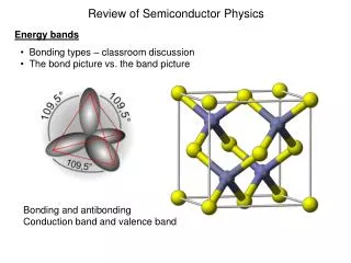
Semiconductor Device Physics Lecture 4 Dr. GauravTrivedi, EEE Department, IIT Guwahati
Electron kinetic energy Ec Increasing electron energy Increasing hole energy Ev Hole kinetic energy Potential vs. Kinetic Energy • Ec represents the electron potential energy:
Band Bending • The potential energy of a particle with charge –q is related to the electrostatic potential V(x): • Since Ec, Ev, and Ei differ only by an additive constant
Band Bending • Until now, Ec and Ev have always been drawn to be independent of the position. • When an electric field E exists inside a material, the band energies become a function of position. E Ec Ev x • Variation of Ec with position is called “band bending”
Diffusion • Particles diffuse from regions of higher concentration to regions of lower concentration region, due to random thermal motion (Brownian Motion).
1-D Diffusion Example • Thermal motion causes particles to move into an adjacent compartment every τ seconds.
Diffusion Currents n p x x Electron flow Hole flow • D is the diffusion coefficient [cm2/sec] Current flow
Total Currents • Drift current flows when an electric field is applied. • Diffusion current flows when a gradient of carrier concentration exist.
Current Flow Under Equilibrium Conditions • In equilibrium, there is no net flow of electrons or : • The drift and diffusion current components must balance each other exactly. • A built-in electric field of ionized atoms exists, such that the drift current exactly cancels out the diffusion current due to the concentration gradient.
Ec(x) EF Ev(x) Current Flow Under Equilibrium Conditions • Consider a piece of non-uniformly doped semiconductor: n-type semiconductor Decreasing donor concentration • Under equilibrium, EF inside a material or a group of materials in intimate contact is not a function of position
Einstein Relationship between D and m • But, under equilibrium conditions, JN = 0 and JP = 0 Similarly, • Einstein Relationship • Further proof can show thatthe Einstein Relationship is valid for a non-degenerate semiconductor, both in equilibrium and non-equilibrium conditions.
Example: Diffusion Coefficient • What is the hole diffusion coefficient in a sample of silicon at 300 K with p = 410 cm2 / V.s ? • Remark:kT/q= 25.86 mVat room temperature
Recombination–Generation • Recombination: a process by which conduction electrons and holes are annihilated in pairs. • Generation: a process by which conduction electrons and holes are created in pairs. • Generation and recombination processes act to change the carrier concentrations, and thereby indirectly affect current flow.
Generation Processes Band-to-Band R–G Center Impact Ionization Release of energy ET: trap energy level • Due to lattice defects or unintentional impurities • Also called indirect generation EG • Only occurs in the presence of large E
Recombination Processes Band-to-Band R–G Center Auger Collision • Rate is limited by minority carrier trapping • Primary recombination way for Si • Occurs in heavily doped material
Phonon Photon Photon Direct and Indirect Semiconductors Ec Ec Ev Ev GaAs, GaN (direct semiconductors) Si, Ge (indirect semiconductors) • Large change in momentum is required for recombination • Momentum is conserved by mainly phonon (vibration) emission + photon emission • Little change in momentumis required for recombination • Momentum is conserved by photon (light) emission
Values under arbitrary conditions Deviation from equilibrium values Equilibrium values Excess Carrier Concentrations • Positive deviation corresponds to a carrier excess, while negative deviations corresponds to a carrier deficit. • Charge neutrality condition:
“Low-Level Injection” • Often, the disturbance from equilibrium is small, such that the majoritycarrier concentration is not affected significantly: • For an n-type material • For a p-type material • Low-level injection condition • However, the minority carrier concentration can be significantly affected.
Indirect Recombination Rate • Suppose excess carriers are introduced into an n-typeSi sample by shining light onto it. At time t = 0, the light is turned off. How does p vary with time t > 0? • Consider the rate of hole recombination: NT : number of R–G centers/cm3 Cp : hole capture coefficient • In the midst of relaxing back to the equilibrium condition, the holegeneration rate is small and is taken to be approximately equal to its equilibrium value:
Indirect Recombination Rate • The net rate of change in p is therefore: where • For holes in n-type material • Similarly, where • For electrons in p-type material
Minority Carrier Lifetime • The minority carrier lifetimeτis the average time for excess minority carriers to “survive” in a sea of majority carriers. • The value of τ ranges from 1 ns to 1 ms in Si anddepends on the density ofmetallic impurities and the density of crystalline defects. • Thedeep trapsoriginated from impurity and defects capture electrons or holes to facilitate recombination and are calledrecombination-generation centers.
Example: Photoconductor • Consider a sample of Si at 300 K doped with 1016 cm–3 Boron, with recombination lifetime 1 μs. It is exposed continuously to light, such that electron-hole pairs are generated throughout the sample at the rate of 1020 per cm3 per second, i.e. the generation rate GL = 1020/cm3/s. • c) What are p and n? • d) What are np product? • Note: The np product can be very different from ni2 in case of perturbed/agitated semiconductor
Net Recombination Rate (General Case) • For arbitrary injection levels and both carrier types in a non-degenerate semiconductor, the net rate of carrier recombination is: where • ET : energy level of R–G center