Download
1 / 20
200 likes | 326 Views
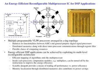
Reconfigurable DSP Project. The ChooChoo: Final Design Review Capital-Architecture School of Electrical and Computer Engineering Georgia Institute of Technology. MPEG II Decoder. Team Members. Pranav Anbalagan Theresa Baker Jishnu Battacharjee Sudipto Chakraborty. Requirements.

E N D
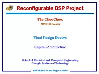
Reconfigurable DSP Project The ChooChoo: Final Design Review Capital-Architecture School of Electrical and Computer Engineering Georgia Institute of Technology MPEG II Decoder FDR--ECE6276 Class Project 12/06/00
Team Members • Pranav Anbalagan • Theresa Baker • Jishnu Battacharjee • Sudipto Chakraborty FDR--ECE6276 Class Project 12/06/00
Requirements • Determine static processor. • Define DSP profiles, memory architecture and control signals for each profile. • Define interconnections between static processor and profiles. • Provide needed assistance during system testing. FDR--ECE6276 Class Project 12/06/00
Schedule • 11/03/00 – 12/06/00: Provide any requested assistance during testing • 11/03/00 : Profiles and static processor picked • 11/08/00 : Defined hardware profiles. Provided DLX hardware details. Provided details for DLX software tools. • 11/10/00 : Finalized DSP Hardware Details. Defined overall memory architecture FDR--ECE6276 Class Project 12/06/00
Schedule (cont.) • 11/12/00 : clear data and control flow issues with DP1 and decoder group • 11/15/00 :Reservation Tables for profiles1,2,3 (with decoder group & ISA) , PDR, Web-site • 12/01/00 : CDR • 12/04/00 : Final report • 12/06/00 : Final Design Review FDR--ECE6276 Class Project 12/06/00
Task Distribution Pranav Anbalagan: Develop profile 3 architecture and control signals and coordinate with Algorithm, DP1, Decoder and ISA groups. Theresa Baker: Provide code and tools for the DLX processor, help with DLX compilation and simulation issues, website development, and coordinate with SIS, SIH and DP2 groups. FDR--ECE6276 Class Project 12/06/00
Task Distribution (cont.) Jishnu Bhattacharjee: Develop profile 1 and 2 architecture and control signals and coordinate with Algorithm, DP1, Decoder and ISA groups. Sudipto Chakraborty: Develop profile 1 and 2 architectures and control signals and coordinate with Algorithm, DP1, Decoder, and ISA groups. FDR--ECE6276 Class Project 12/06/00
Early Architectural Decisions We chose to have 3 separate profile data paths, each with their own decoder. The alternate choice was to have one data path and the decoder make sure each profile ran correctly on this data path. We decided that, in the timeframe we had for this project, that the decoder for the alternate design would be too complex. We decided to have one global data memory shared between all three profiles. Each profile needed its own instruction memory, but sharing a data memory significantly reduced the amount of state that needed to be saved during a change of profile. FDR--ECE6276 Class Project 12/06/00
DLX Architecture Overview FDR--ECE6276 Class Project 12/06/00
Reasons for Choosing the DLX • Source code was available. • Software tools for compilation and assembling were available. • There was a person who already had a good knowledge of the design and could help other groups. • Originally the architecture group thought the commands for the profiles would be processed through the static processor and the DLX offered a known way to do that. FDR--ECE6276 Class Project 12/06/00
Profile Definitions • Profile 1: IDCT • Profile 2: Inverse Quantization & Inverse Zigzag • Profile 3: Motion Compensation • Profiles 1 and 2 are modifications of Motorola-56k family with a Data Processor similar to ADSP2100. Profile 3 was kept similar to the Texas Instruments TMS320C6x architecture FDR--ECE6276 Class Project 12/06/00
Reasons for Choosing these Profiles • We looked at the C code provided by the algorithm group and determined the maximum parallelism that could be extracted. • Given the time constraints of this project we were trying to keep each profile as simple as possible. • We wanted to maximize the reusability of the code between the profiles and the DLX. FDR--ECE6276 Class Project 12/06/00
Reasons for Choosing Profiles (cont.) • For IDCT we are realized that a part of the code was similar to the FFT Butterfly and we used the ADSP 21020 core that was described in our text as being efficient for the Butterfly. • Profile 2 was kept incrementally different from profile 1 as Inverse Quantization and Inverse Zig Zag do not require any sort of sophisticated computations. • Profile 3 was chosen likewise since TMS320C6x architecture is highly efficient for motion compensation according to Texas Instruments. FDR--ECE6276 Class Project 12/06/00
Profile 1 Architecture FDR--ECE6276 Class Project 12/06/00
Profile 2 Architecture FDR--ECE6276 Class Project 12/06/00
Profile 3 Architecture FDR--ECE6276 Class Project 12/06/00
Technical Difficulties • Problem: Implementing the parallel instructions needed to get full benefit out of the defined profiles. • Resolution: The Software Integration team will do some manual modifications of the code provided by lcc and TIM in order to implement those instructions. FDR--ECE6276 Class Project 12/06/00
Technical Difficulties (cont.) • Problem: Some of the libraries used in the DLX are not available in MaxPlusII. The vhdl files were originally written for use by vss. • Resolution: The DP2 team, with some assistance from our team, tried to make the modifications needed for MaxPlusII. However, the groups decided that the DLX was not needed to complete the project and in the interest of time it wasn’t used. However, before it was discarded the entire processor did compile under MaxPlusII so it could be considered for any future development of the project. FDR--ECE6276 Class Project 12/06/00
Original Architecture Changes The DLX processor wasn’t used. A lot of parallelism was stripped from the profiles. Time did not allow for the development of the complex design needed to support parallelism. Some slight changes in access ability were made to the global data memory design. Due to the absence of significant parallelism, the bounds did not need to be calculated. FDR--ECE6276 Class Project 12/06/00
Lessons Learned • That an optimized product is not always possible within the time constraints. Oftentimes, within tight time constraints, you must tradeoff optimization for quick implementation. • Be careful which tools you use for your designs. Not all design tools have the same functionality. • Communication between groups is vital, but sometimes difficult to maintain. FDR--ECE6276 Class Project 12/06/00