Download
1 / 29
290 likes | 400 Views
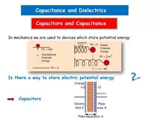
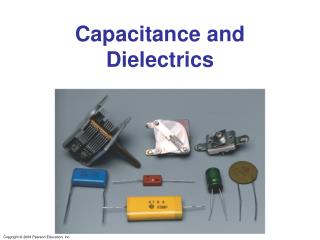
Capacitors and Dielectrics. Ch 26. Capacitors. Conductors are commonly used as places to store charge You can’t just “create” some positive charge somewhere, you have to have corresponding negative charge somewhere else Definition of a capacitor:

E N D
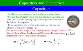
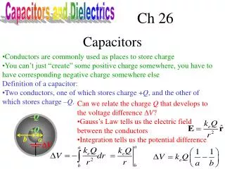
Capacitors and Dielectrics Ch 26 Capacitors • Conductors are commonly used as places to store charge • You can’t just “create” some positive charge somewhere, you have to have corresponding negative charge somewhere else • Definition of a capacitor: • Two conductors, one of which stores charge +Q, and the other of which stores charge –Q. • Can we relate the charge Q that develops to the voltage difference V? • Gauss’s Law tells us the electric field between the conductors • Integration tells us the potential difference –Q +Q b a V
Capacitance • The relationship between voltage difference and charge is always linear • This allows us to define capacitance • Capacitance has units of Coulomb/Volt • Also known as a Farad, abbreviated F • A Farad is a very large amount of capacitance • Let’s work it out for concentric conducting spheres: What’s the capacitance of the Earth, if we put the “other part” of the charge at infinity?
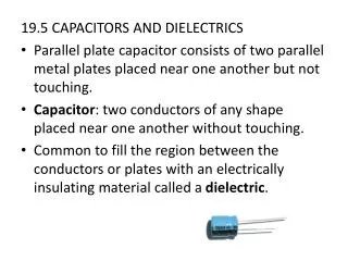
Parallel Plate Capacitors A • A “more typical” geometry is two large, closely spaced, parallel conducting plates • Area A, separation d. • Let’s find the capacitance: • Charge will all accumulate on the inner surface • Let + and – be the charges on each surface • As we already showed using Gauss’s law, this means there will be an electric field given by • If you integrate the electric field over the distance d, you get the potential difference d Circuit symbol for a capacitor: To get a large capacitance, make the area large and the spacing small
JIT Ans d
JIT Quick Quiz 26.2 Ans a (increase)
Capacitors in Parallel When we close the switch, how much charge flows from the battery? A) 36 C B) 4 C C) 18 C D) 8 C E) 10 C 2 V 3 F 6 F • The voltage difference across each capacitor will be 2 V. • When capacitors are connected like this at both ends, we say they are connected in parallel • The combined capacitors act like a single capacitor with capacitance:
Capacitors in Series When we close the switch, which capacitor gets more charge Q on it? A) The one with the bigger capacitance B) The one with the smaller capacitance C) They get the same amount of charge D) Insufficient information V1 V2 +Q -Q +Q -Q C1 C2 V • Charge flows to the left side of the first capacitor • Since capacitors have balanced charge, the rightside must have the equal and opposite charge • The only place it can get this charge is the left side of the right capacitor • The charges on the second capacitor are also balanced • The voltage difference on each capacitor is not the same, since only one end is connected. But the charge is the same. • The two voltages differences can be added together
Series and Parallel C1 C2 C1 C2 C4 C2 C3 C1 C5 • When two circuit elements are connected at one end, and nothing else is connected there, they are said to be in series • When two circuit elements are connected at both ends, they are said to be in parallel • These formulas work for more than two circuit elements as well.
JIT Quick Quiz 26.3 Ans a
Ans B Ans C Ans A,B
Sample Problems What is the capacitance of the structure shown at left? A) 180 F B) 120 F C) 30 F D) 20F E) none of the above 60 F 60 F 60 F • They are connected end-to-end, so they are in series • Now add a wire across the middle. The two ends of the middle capacitor are at the same potential; therefore, there is no charge on this capacitor • You might as well ignore it
Complicated Capacitor Circuits 2 6 • For complex combinations of capacitors, you can replace small structures by equivalent capacitors, eventually simplifying everything The capacitance of the capacitors in pF below is marked. What is the effective capacitance of all the capacitors shown? • Capacitors 1 and 5 are connected at both ends- therefore they are parallel 4 3 5 1 2 • Capacitors 3 and 6 are connected at just one end – therefore they are series 10 V • All three capacitors are now connected at both ends – they are all in parallel
Energy in a capacitor • Suppose you have a capacitor with charge q already on it, and you try to add a small additional charge dq to it, where dq is small. How much energy would this take? • The side with +q has a higher potential • Moving the charge there takes energy • The small change in energy is: –q +q • Now, imagine we start with zero charge and build it up gradually to q = Q • It makes sense to say an uncharged capacitor has U = 0 dq
Energy in a capacitor (2) 20 V 1 F 2 F • Capacitors in parallel have the same voltage difference V • The larger capacitor has more energy For each of the two circuits, which capacitor gets more energy in it? A) The 1 F capacitor in each circuit B) The 2 F capacitor in each circuit C) The 1 F capacitor in the top circuit, the 2 F capacitor in the bottom circuit D) The 2 F capacitor in the top circuit, the 1 F capacitor in the bottom circuit E) They are equal in each circuit 1 F 2 F 20 V • Capacitors in series have the same charge Q • The smaller capacitor has more energy
Energy density in a capacitor Suppose you have a parallel plate capacitor with area A, separation d, and charged to voltage V. (1) What’s the energy divided by the volume between the plates? (2) Write this in terms of the electric field magnitude • Energy density is energy over volume A d • We can associate the energy with the electric field itself • This formula can be shown to be completely generalizable • It has nothing in particular to do with capacitors
JIT Ans b
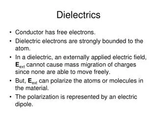
Dielectrics in Capacitors + + + + + + + + + + + + –––––––––––– • What should I put between the metal plates of a capacitor? • Goal – make the capacitance large ++++++++++++ • The closer you put the plates together, the bigger the capacitance • It’s hard to put things close together – unless you put something between them • When they get charged, they are also very attracted to each other • Placing an insulating material – a dielectric – allows you to place them very close together • The charges in the dielectric will also shift • This partly cancels the electric field • Small field means smaller potential difference • C = Q/V, so C gets bigger too
Choosing a dielectric • What makes a good dielectric? • Have a high dielectric constant • The combination 0 is also called , the permittivity • Must be a good insulator • Otherwise charge will slowly bleed away • Have a high dielectric strength • The maximum electric field at which the insulator suddenly (catastrophically) becomes a conductor • There is a corresponding breakdown voltage where the capacitor fails
JIT Ans a
Consider isolated capacitor Ans B Consider isolated capacitor after charging Ans A Ans A
What are capacitors good for? • They store energy • The energy stored is not extremely large, and it tends to leak away over time • Gasoline or fuel cells are better for this purpose • They can release their energy very quickly • Camera flashes, defibrillators, research uses • They resist changes in voltage • Power supplies for electronic devices, etc. • They can be used for timing, frequency filtering, etc. • In conjunction with other parts