
Network Security
E N D
Presentation Transcript
Lecture 1, Part 1 Introduction to Networking Network Security
Objectives of Lecture • Show how networks can be understood using a layered approach. • Introduce the OSI seven layer reference model. • Introduce the concepts of internetworking and routing. • Understand the difference between network protocols and services. CINS/F1-01
Contents 1.1 Extended example: how the Internet protocols fetch a web page 1.2 The concept of protocol layering 1.3 Internetworking and routing 1.4 The OSI seven layer model
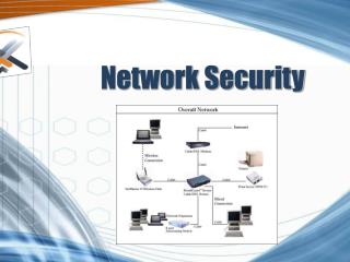
1.1 Internet Protocols How does a web browser application retrieve data from a web server? Network Web Server Web Browser
Application Layer • Users invoke applications which “speak” using application protocol. • Applications interact with a transport protocol to send or receive data. • Application protocol in our example: Hypertext Transfer Protocol (HTTP). • Other application protocols: FTP, SMTP, DNS, SMB, …
Application Layer Example • HTTP outline: • GET /directory/dirsearch.html HTTP/1.1 • Host: news.bbc.co.uk • Other fields also included (e.g. client application identifier, encoding methods,…) HTTP Message GET /directory/dirsearch.html HTTP/1.1 Host: news.bbc.co.uk
Transport Layer • Provides end-to-end communication between applications. • Transport Protocol: Transport Control Protocol (TCP) • a reliable, connection-oriented transport protocol. • Divides stream of application messages into packets. • Interacts with Internet Layer to send or receive data. • In general, a transport protocol may be • reliable or unreliable, • connection-oriented or connectionless, • and flow may or may not be regulated. • Others: UDP, ICMP.
Transport Layer Example • TCP outline: • Source Port: 1081 • Destination Port: 80 • Checksum: 0xa858 • Other header fields and payload TCP payload TCP header Src: 1081 Dst: 80 Chksum: 0xa858 GET /directory/dirsearch.html HTTP/1.1 Host: news.bbc.co.uk HTTP Message
Internet Layer • Responsible for routing communications between one machine and another. • Accepts requests to send packets to destination address. • Internet Protocol (IP) encapsulates packets in IP datagram with IP header and uses routing algorithm to decide whether to send directly or indirectly.
Internet Layer Example • IP outline: • Time to live: 128 • Header checksum: 0x57d1 • Source: pelican (192.168.0.40) • Destination: news.bbc.co.uk (192.168.0.50) • Other header fields and payload IP payload IP datagram header Src: 192.168.0.40 Dst: 192.168.0.50 TTL: 128 Src: 1081 Dst: 80 Chksum: 0xa858 GET /directory/dirsearch.html HTTP/1.1 Host: news.bbc.co.uk TCP header HTTP Message
Network Interface Layer • Accepts IP datagrams and prepares for transmission over specific physical network. • Maybe a simple device driver (e.g. an Ethernet driver) or a complex subsystem with further data link protocols (e.g. in an ATM network). • Output of network interface layer is a signal suitable for transmission on a particular physical medium.
Network Interface Layer Example • Ethernet outline: • Destination: 00:a0:cc:54:1d:4e • Source: 00:e0:81:10:19:fc • Type: IP • Other header fields and payload Ethernet Frame Src: 00:e0:81:10:19:fc Dst: 00:a0:cc:54:1d:4e Type: IP Src: 192.168.0.40 Dst: 192.168.0.50 TTL: 128 Src: 1081 Dst: 80 Chksum: 0xa858 GET /directory/dirsearch.html HTTP/1.1 Host: news.bbc.co.uk
Physical Layer • A layer representing the actual communications medium. • Could be an ethernet cable, optical fibre, wireless link, telephone wire or even a carrier pigeon (http://www.ietf.org/rfc/rfc1149.txt) • Sometimes not considered as a separate layer in TCP/IP networking; sometimes not considered part of TCP/IP at all. • Thus creating confusion over whether there are really 4 or 5 layers in TCP/IP.
At The Server • The server contains a set of layers matching those at the client: • The physical signal is presented to the server’s network interface layer which reconstructs the ethernet frame. • The network interface layer extracts an IP datagram and passes it up to the Internet layer. • The Internet layer checks the datagram, extracts a TCP segment and passes it up to the transport layer. • The transport layer checks for errors and passes the TCP payload (an http message) onto the application layer. • The web server at the application layer receives the http message and processes it. • Return messages from web server to web browser are handled in the same way.
1.2 Protocol Layering Host A Host B Application Layer Application Layer Message Transport Layer Transport Layer Packet Internet Layer Internet Layer Datagram Network Interface Layer Network Interface Layer Frame Physical Network
Protocol Layering Web Browser Web Server Application Layer Application Layer HTTP Message Transport Layer Transport Layer TCP Packet Internet Layer Internet Layer IP Datagram Network Interface Layer Network Interface Layer Ethernet Frame Physical Network
Protocol Hierarchies • Protocols are stacked vertically as series of ‘layers’. • Each layer offers services to layer above through an interface, shielding implementation details. • Layer n on one machine communicates with layer n on another machine (they are peer processes/entities) using Layer n Protocol. • The entire hierarchy is called a protocol stack • e.g. the TCP/IP protocol stack
Layers, Protocols & Interfaces Layer n/n+1 interface Layer n/n+1 interface Layer n protocol Layer n Layer n Layer n-1/n interface Layer n-1/n interface Layer 2/3 interface Layer 2/3 interface Layer 2 protocol Layer 2 Layer 2 Layer 1/2 interface Layer 1/2 interface Layer 1 protocol Layer 1 Layer 1 Physical communications medium
Layer and Interface Design • An important design objective is ‘clean’ interfaces, having minimal set of well-defined services. • Use of protocol layering and clean-cut interfaces enables: • easy replacement of individual layers • designers and implementers to focus on solving one sub-problem at a time • independent implementations of the same layer to inter-operate • minimisation of inter-layer communications • diagnosis of faults, errors, congestion,…
Virtual & Actual Communications • Important to understand difference between: • virtual and actual communications, • protocols and interfaces. • Peer processes ‘think’ of communications as being ‘horizontal’ using protocol. • Actual communications is via interfaces (and the physical communications medium). • Peer process idea is key to network design.
Protocol Layering – The Downside • Protocol layering does not solve all networking problems! • Some issues need to be addressed at many layers, e.g: • need to address data (say who it’s for), • possible need for setting up connections, • data transfer rules (simplex, half-duplex, ...), • error management, • deal with message component re-ordering, • flow control, • routing. • Layering can introduce inefficiencies.
1.3 Internetworking and Routing • No single networking technology can satisfy all requirements. • Universal interconnection is desired. • Protocols allow communication between nodes without understanding underlying mechanisms. • Internetworking is the process by which a group of disparate, heterogenous networks can be linked to form a single logical network. • The Internet is just such a collection • universal interconnection is achieved through use of coordination of IP addressing and use of IP protocol.
Routing Routing is the mechanism used to transfer data between networks to reach the correct destination. Network B Router Web Server Network A In TCP/IP, routing takes place at the IP layer: routers are not aware of transport and application layers. Web Browser
Protocol Layering and Routing Host A Host B Application Layer Application Layer HTTP Message Transport Layer Transport Layer TCP Packet Router Internet Layer Internet Layer Internet Layer IP Datagram IP Datagram NetworkInterface Network Layer Network Interface Ethernet Frame Ethernet Frame Physical Network Physical Network
1.4 The OSI Reference Model • OSI Reference Model – an internationally standardised network architecture. • An abstract representation of an ideal network protocol stack; not used in real networks. • OSI = Open Systems Interconnection. • Specified in ISO 7498-1. • Model has 7 layers.
The OSI Model Layer 7 Application Layer Layer 6 Presentation Layer Layer 5 Session Layer Layer 4 Transport Layer Layer 3 Network Layer Layer 2 Data Link Layer Layer 1 Physical Layer
Lower/Upper Layers • Layers 1-4 often referred to as lower layers. • Layers 5-7 are the upper layers. • Lower layers relate more closely to the communications technology. • Layers 1 – 3 manage the communications subnet. • the entire set of communications nodes required to manage comms. between a pair of machines. • Layers 4 – 7 are true ‘end-to-end’ protocols. • Upper layers relate to application.
Layer 7: Application Layer • Home to wide variety of protocols for specific user needs, e.g.: • virtual terminal service, • file transfer, • electronic mail, • directory services.
Layer 6: Presentation Layer • Concerned with representation of transmitted data. • Deals with different data representations. • ASCII or EBCDIC, • one’s complement or two’s complement, • byte ordering conventions, • floating point conventions (IEEE or proprietary). • Also deals with data compression.
Layer 5: Session Layer • Allows establishment of sessions between machines, e.g. to • allow remote logins • provide file transfer service. • Responsible for: • dialogue control • which entity sends when with half-duplex communications. • token management • E.g. control which entity can perform an operation on shared data. • synchronisation • E.g. insertion of checkpoints in large data transfers.
Layer 4: Transport Layer • Basic function is to take data from Session Layer, split it up into smaller units, and ensure that the units arrive correctly. • Concerned with efficient provision of service. • maybe multiple connections per session or multiple sessions per connection. • The Transport Layer also determines the ‘type of service’ to provide to the Session Layer. • most commonly, error-free, point-to-point, with guarantee of correct ordering of data. • could be transport of isolated messages only (no ordering guarantees) or broadcast.
Layer 3: Network Layer • Provides uniform addressing scheme for network addresses. • Shields upper layers from details of lower layers. • A key responsibility is control of routing. • Routing can be based on: • static tables, • determined at start of session, • highly dynamic (varying for each packet depending on network load). • Also responsible for congestion control and usage monitoring.
Layer 2: Data Link Layer • Provides reliable, error-free service on top of raw Layer 1 service. • corrects errors at the ‘bit’ level. • Breaks data into frames. • requires creation of frame boundaries using special bit sequences. • Frames used to manage errors via acknowledgements and selective frame retransmission.
Layer 1: Physical Layer • Concerned with bit transmission over physical channel. • Issues include: • definition of 0/1, • whether channel simplex/duplex, • connector design. • Mechanical, electrical, procedural matters.
Internet Protocols vs OSI Application Application 7 Presentation 6 5 Session 5 TCP Transport 4 4 3 IP Network 3 Network Interface 2 Data Link 2 Hardware Physical 1 1
Services in the OSI Model • In OSI model, each layer provide services to layer above, and ‘consumes’ services provided by layer below. • Active elements in a layer are called entities. • Entities in same layer in different machines are called peer entities.
Services and Protocols • Service = set of primitives provided by one layer to layer above. • Service defines what layer can do (but not how it does it). • Protocol = set of rules governing data communication between peer entities, i.e. format and meaning of frames/packets. • Service/protocol decoupling very important.
Layering Principles n+1 PDU (n+1) Entity Service User (n+1) Entity Service User Layer n+1 protocol Layer n Service Access Point (SAP) SDU (n) Entity Service Provider (n) Entity Service Provider Layer n protocol n PDU PDU - Protocol Data Unit SDU - Service Data Unit
Connections • Layers can offer connection-oriented or connectionless services. • Connection-oriented like telephone system. • Connectionless like postal system. • not all applications need connections. • Each service has an associated Quality-of-service (e.g. reliable or unreliable).
Reliability Issues • Reliable services never lose/corrupt data. • Reliable service costs more. • Typical application for reliable service is file transfer. • Typical application not needing reliable service is voice traffic.
Lecture 1, Part 2 Introduction to Network Security IC3 - Network Security
Objectives of Lecture • Understand why security should be a fundamental consideration when designing and operating networks. • Examine the primary enabling threats and fundamental threats to security for networks. • Introduce security services and mechanisms, and show how they can be used to counter threats. • Study the provision of security services at different network layers in ISO7498-2. CINS/F1-01
Contents 1.5 Why network security? 1.6 Security policies for networks 1.7 Security threats for networks 1.8 Security services and mechanisms 1.9 Security services and layers
1.5 Why Network Security? • Organisations and individuals are increasingly reliant on networks of all kinds for day-to-day operations: • e-mail used in preference to letter, fax, telephone for many routine communications. • B2B and C2B e-commerce still growing rapidly. • the Internet is a vast repository of information of all kinds: competitors and their prices, stock markets, cheap flights,…. • increased reliance on networks for supply chains of all kinds: from supermarkets to aircraft components. • utility companies control plant, banks move money, governments talk to citizens over networks. • growth of mobile telephony for voice and data.
Why Network Security? • Networks are becoming increasingly inter-connected and their security consequently more complex: • if I send sensitive data over my internal network, then who else can see it or even alter it? My employees? My competitors? • can a hacker who gets into my internal network then get access to other resources (computer accounts, stored data)? Can he use my network as a stepping-off point for further attacks? I am then liable? • a compelling Internet presence is essential for my company, but if someone can see my website, can they alter it too? • how can consumers trust that a given website is that of a reputable company and not one who will mis-use their credit card details?
Why Network Security? • Safeguarding the confidentiality, integrity and availability of data carried on these various networks is therefore essential. • Authenticity and accountability are often also important: who did what and when? • It’s not only about security of Internet-connected systems. • Insider threats are often more potent than threats originating on the Internet. • It’s not only about TCP/IP networks. • Many networks use special-purpose protocols and architectures. • However TCP/IP dominates in LANs and the Internet.
1.6 Security Policies for Networks • In this and the following sections, we follow the approach of ISO7498-2 • a companion document to ISO7498-1 (the seven layer model), • provides a useful overview of the security issues pertinent to networks, • equips us with a handy set of definitions to fix our terminology.
Security Policies for Networks • In a secure system, the rules governing security behaviour should be made explicit in the form of an Information Security Policy. • Security policy: ‘the set of criteria for the provision of security services’ • essentially, a set of rules • may be very high level or quite detailed. • Security domain: the scope of application of a security policy. • where, to what information and to whom the policy applies.
Security Policies for Networks • A network security policy should interpret the overall Information Security Policy in the context of the networked environment: • Defines what is the responsibility of the network and what is not. • Describes what security is to be available from the network. • Describes rules for using the network. • Describes who is responsible for the management and security of the network.
Generic Security Policy • A generic authorisation policy (from ISO 7498-2): ‘Information may not be given to, accessed by, nor permitted to be inferred by, nor may any resource be used by, those not appropriately authorised.’ • Possible basis for more detailed policy: needs lots of refinement to produce final document: • What information? • What resources? • Who is authorised and for what? • What about availability?