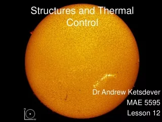
Thermal Control System
Thermal Control System. The Three Mechanisms of Heat Transfer. Conduction - The transfer of heat through a solid Interface Heat Exchangers Cold plates Convection - Transfer through fluids both liquids and gasses Radiation - Transfer through vacuum or empty space

Thermal Control System
E N D
Presentation Transcript
The Three Mechanisms of Heat Transfer • Conduction - The transfer of heat through a solid • Interface Heat Exchangers • Cold plates • Convection - Transfer through fluids both liquids and gasses • Radiation - Transfer through vacuum or empty space • Does not need a vacuum to radiate heat • Radiators
System Overview • Divided into internal and external loops, as well as per module • Divided into 35 and 62 degree loops • 35 degree loop cools all critical systems • 62 degree loop cools all non-essential systems • Maintains a comfortable living and working temperature for the station
Internal TCS system • Cold plates, LCA, Pumps, Interface Heat Exchangers • All systems use water in case of leaking, as it is non toxic, and conducts heat very well.
Cold Plates • Aluminum box conducts heat to water piping within • No power required, all flow is controlled by pump • Solenoid valve can bypass flow if necessary
Internal Pump • Circulates water through the cold plates • Powered by EPS power distribuition • Status, Flow rate, Pressure, Temperature, Voltage, Amperage
Loop Crossover Assembly (LCA) • Allows both 35 and 62 degree loops to be connected within a given module • A single pump can only handle approximately 10 cold plates continuously at a time • Valves adjust flow to Interface Heat Exchangers
Regenerative Heat Exchanger • Only in use when the LCA is activated in single loop mode • The Regenerative Heat Exchanger warms 35 degree loop water before entering 62 degree loop • This is done to prevent condensation in the 62 degree loop
Interface Heat Exchangers • Identical internal and external systems • Intertwined spirals of piping allow heat to conduct between the internal water systems, and the external ammonium systems • Ammonium and water never mix as all heat is conducted through the walls of the piping • Sensors will alert crew to any leak of ammonium that would possibly contaminate the water system.
External Thermal Control System • Interface Heat Exchanger, Pump Package Assembly, TRRJ, Radiator • Uses ammonium to prevent damage to pipes from extreme temperature differences • Ammonium has a lower freezing point than water, however in higher concentrations can prove toxic to the crew
Pump Package Assembly (PPA) • Circulates ammonium through external systems an d water through the internal systems • Only two external loops, one PPA per loop • Powered by EPS loads • Also known as Pump Module Assembly (PMA)
Radiators / TRRJ • Radiators allow heat to radiate into the space environment. • Thermal Radiator Rotation Joint • Acts as a large loop crossover for PPAs
Accumulator • The Accumulator is attached to the PPA • Helps absorb changes in ammonia volume because of different temperatures • Resupplies external loop with ammonium if it is lost
Warning signs of a SOBE • Red indicator lights on the system wall • Increase in ambient temperature and or humidity • Ammonium smell (very obvious) • Contingency of another SOBE
Things to check during a SOBE • Flow Rate • If no fluid is moving, then no heat is either • Loads for faulty pump/PPA • No power = No flow • Ammonium leaks (sensor info) • Toxic to Crew • Reduces flow in external system