Download
1 / 1

E N D
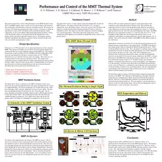
Abstract We present results from a study of the performance of the MMT thermal system. The 6.5-m MMT primary mirror consists of a borosilicate honeycomb structure that is thermally controlled with a forced-air ventilation system. We will give an overview of both the measurement and control systems. Our goal is to define an algorithm for control of the ventilation system such that the primary mirror temperature closely tracks ambient while minimizing thermal gradients. Future work will include a study of correlations between the thermal state of the primary mirror and both seeing and wavefront errors. The thermal system is currently controlled by the telescope operators, but the results from this work will assist in fully automating the system. Ventilation Control The figure below shows a screen capture of the main thermal GUI used by the MMT operators. The upper section of the GUI shows a 14 x 14 map of temperatures across the primary mirror. The lower section of the GUI allows the operator to modify the information displayed in the GUI and to control the ventilation system. The operators control the ventilation system by changing two coolant temperatures. They then monitor the temperatures of the conditioned air through the system and the air temperature in the vicinity of the primary mirror. Analysis Gibson (2003) provided a quantitative analysis of the performance of the ventilation system during the month of January 2003. He found that the isothermal criterion was never met during that month. However, the peak-to-valley differences for the front-plate were frequently less than 0.4 ˚C with the larger gradients typically observed only at the beginning of the night. The RMS differences were repeatedly less than 0.1 ˚C and were only above 0.4 ˚C at the beginning of three nights. He also found that the primary mirror was in compliance with primary-to-ambient difference criterion approximately 15% of the time. One caveat is that the stability of the MMT E-series thermocouples is not well known. Although the ventilation system does not yet meet the design specifications, the ultimate measure of performance is the image quality. The MMT often delivers good image quality when not meeting the thermal design specifications. There are likely multiple reasons for this. First, the primary-to-ambient (mirror seeing) requirement was based on empirical results from Racine et al. (1991) which did not account for the effect of wind. Zago (1995,1997) found that even a moderate wind could greatly reduce mirror seeing. Second, the isothermality criterion was specified for the very best seeing conditions at the MMT. A seeing histogram for the MMT shows that the best seeing is achieved only 2.5% of the time and that the median seeing is 0.71” FWHM. Finally, since the MMT employs a wavefront sensor and active control of the primary (see Pickering et al. in this meeting), wavefront errors that result from thermal non-uniformities can be corrected. Therefore, a combination of good thermal control and selected wavefront sensing can deliver very good image quality. We are comparing data on the thermal state of the primary with wavefront sensor data to understand when wavefront sensing is most needed. We spent three nights in January, 2004 measuring the temperature dependent defocus for the MMT. We found that at the beginning of the night, when the temperature was changing most rapidly, the defocus followed the predicted defocus. However, as the temperature stabilized, we found that the defocus deviated from the predicted defocus. We were unable to correlate this defocus with any of the low order Zernike terms. We are still investigating the cause of the discrepancy. A plot of the data is show below. Performance and Control of the MMT Thermal System The MMT Main Thermal GUI • Design Specifications • Fabricant et al. (1999) presented a set of optical specifications for the converted MMT. The optical error budget was specified to provide an image quality that would match the best seeing conditions expected at the MMT site. This requires the telescope to deliver images of 0.23” FWHM and for the combination of the telescope and atmosphere to produce a detected image of 0.32” FWHM. Thermal sources are allotted a fraction of the error budget. The result was a set of specifications for the forced-air ventilation system. The design of the ventilation system was largely driven by similar requirements provided in Cheng & Angel (1988). One goal of the current study is to understand how well those specifications have been met during the three years the system has operated. The following are the specifications from Fabricant et al.: • Temperature Dependent Defocus (f/9): -64 μm/˚C • Thermal Gradients within the Primary: < 0.1 ˚C • Primary-to-Ambient Temperature Difference: < 0.15 ˚C MMT Ventilation System The figure below shows a schematic of the MMT ventilation system. Air is drawn into the system through dust filters at the main centrifugal blower located in a support building. The air travels through a 24” flexible duct into the “shop” heat exchanger, which circulates chilled glycol from a Carrier chiller. The duct then runs underground into the basement or “pit” of the telescope. The air passes through a second heat exchanger which circulates chilled liquid from the Carrier and a Neslab chiller. The conditioned air enters the main telescope chamber through a rotating duct. Two flexible ducts direct the air into the primary mirror cell where it is distributed by a manifold to 150 jet ejectors. The Thermal Evolution During a Single Night G. G. Williamsa, J. D. Gibsona, S. Callahanb, D. Blancoa, J. T. Williamsa,b, and P. Spencera (aMMT Observatory, bLBT Observatory) OSS Temperature and Defocus A Schematic of the MMT Ventilation System Jet Ejector & Mirror Cell Cut Away MMT Jet Ejectors The figure to the right illustrates the design of the MMT jet ejectors. The jet ejectors are attached to holes in the upper-plate of the cell. Pressurized air from the ventilation system is directed through the jet ejector nozzle. This draws air from the upper plenum, the area between the cell top-plate and the mirror back-plate, through the jet ejector where it mixes with the conditioned air. The lower plenum fills with pressurized air, which is forced through the ventilation nozzles into the 1020 honeycomb cells of the primary. The air circulates through the honeycomb cell and exits into the upper plenum. A set of six exhaust ejectors allow for a fraction of the air to be exhausted from the cell; 90% of the air is recirculated. Conclusions Cheng & Angel (1988) and Fabricant et al. (1999) provided a set of specifications for the thermal control of the MMT primary mirror. We find that the ventilation system is not yet performing to those levels. However, results from this study will be used to guide the MMT operators on better control of the system. This will result in more frequent compliance with the original specifications. The MMT does deliver good image quality even when the design specifications are not met. Since there is active control of the primary and wavefront sensing, the original specifications may be too stringent for most “normal” operating conditions.