Download

1 / 12
120 likes | 176 Views
Explore the innovative field mapping methodology utilizing the ATLAS Field Mapper for precise magnetic field analysis and corrections. Dive into the Mapper machine, software, simulations, corrections, and future plans. Discover details on the solenoid field shape, objectives, and mapping techniques for ATLAS Inner Detector alignment.

E N D
Solenoid Magnetic Field Mapping • Introduction • Mapper machine • Mapper software • - Simulation • - Corrections • - Fitting • Future work Paul S Miyagawa University of Manchester
The Principals • Martin Aleksa (project coordinator) • Marcello Losasso (engineering design) • Felix Bergsma (Hall probes + motors) • Heidi Sandaker (DAQ) • Steve Snow (NMR probes + software) • John Hart + Paul S Miyagawa (software) ATLAS ID alignment meeting
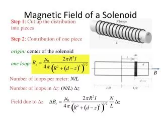
Magnetic Field Shape • z-component dominant near centre of solenoid • r-component more important near ends of coil • Field from magnetised iron only 4.5% of total • Bending power defined as Bz – Br z / r ATLAS ID alignment meeting
Objectives • Momentum scale will be dominant uncertainty in W mass measurement • Momentum accuracy depends on ∫r(rmax - r)Bzdr, so field at intermediate radii is most important • Need to measure bending power integral of magnetic field to 0.05% accuracy • Field B may be described by a scalar potential satisfying Laplace’s equation, 2 = 0 • Sufficient to measure B on the surface of a cylinder (including the ends) surrounding the tracker ATLAS ID alignment meeting
Field Mapper Machine • Two propeller arms which rotate in phi • Carriage slides in z along rails • Up to 25 Hall probes on each arm on both sides • Cross-checks between probes on opposite sides of same arm • Also have cross-checks between arms • Machine measures field inside solenoid before ID installed • Also have 4 NMR probes permanently fixed to solenoid to set overall scale ATLAS ID alignment meeting
Field Mapper Software • Convert raw data to physical units • Correct for time drifts in solenoid current • Correct for time drifts in individual Hall probes • Convert to a regular grid • Fit data with two methods: geometrical fit and Fourier-Bessel parametrisation • Use fits to correct normalization and alignment of Hall probes ATLAS ID alignment meeting
Simulation of Raw Data • Field calculated from solenoid of expected dimensions • Magnetisation due to magnetic material from outside Inner Detector • Random walk with time for solenoid current and Hall probe measurements • Random errors for each measurement ATLAS ID alignment meeting
Correction for Current Drift • Average B-field of 4 NMR probes used to calculate “actual” solenoid current • Scale all measurements to a reference current (7600 A) • Effect of drift in current removed • Calibration capable of coping with any sort of drift ATLAS ID alignment meeting
Correction for Hall Probe Drift • Mapping machine regularly returns to fixed calibration positions • Near coil centre to calibrate Bz • Near coil end for Br • No calibration of B • Each channel is calibrated to a reference time (beginning of run) • Scaling factors from calibration points used to determine scalings for measurements between calibrations ATLAS ID alignment meeting
Geometrical Fit • Sum of simple fields known to obey Maxwell’s equations • Long-thin coil (5 mm longer, 5 mm thinner than nominal) • Short-fat coil (5 mm shorter, 5 mm fatter) • Four terms of Fourier-Bessel series (for magnetisation) • Use Minuit for 2 fit to data • Fit gives information about position, shape, etc of coil ATLAS ID alignment meeting
Fourier-Bessel Fit • General fit able to describe any field obeying Maxwell’s equations • Uses large number of parameters obtained by direct calculation • Calculate Fourier terms from Bzon outer cylinder • Fit cosh(λz) terms to ends of cylinder • Fit Br to find z-independent component of field • Poor fit indicates measurement errors rather than incorrect model ATLAS ID alignment meeting
Future Plans • Simulate other effects • Geometrical misalignments • Mechanical deformations • Systematic measurement errors • Readout errors, e.g., missing measurements • Mapper machine scheduled to take data in late February 2006 • Add magnetisation due to magnetic materials in Inner Detector • Deliver final field map on a cylindrical lookup grid • Need to link ID field map to other B-field maps ATLAS ID alignment meeting